YS24X_Ope_E.pdf - 第58页
1-21 1 Part names and functions n Single-lane/Dual-lane Sensor layout N Lane 1 N Lane 2 Entrance sensor N 01008C 5 Exit sensor N 01008D3 Standby position sensor 1 N 01008C 0 Standby position sensor 2 N 01008C 7 Board s…
1-20
1
Part names and functions
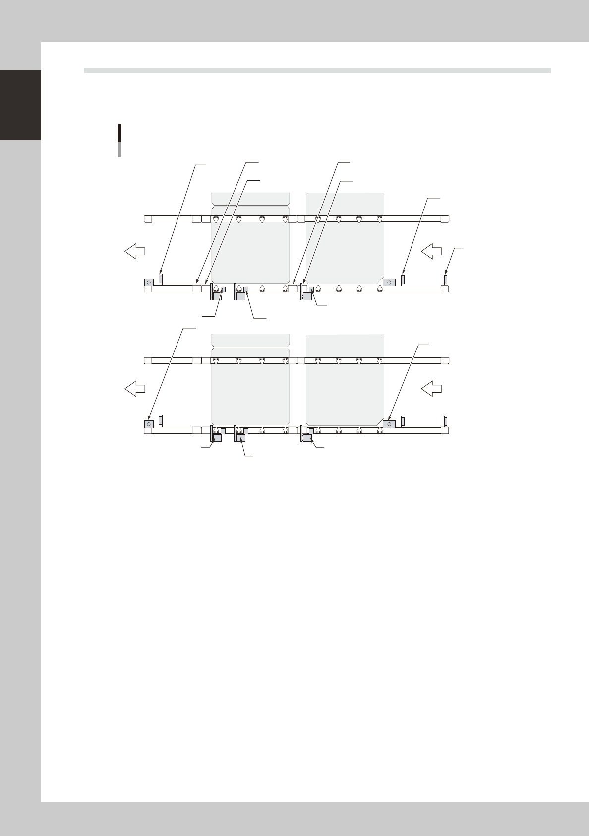
5.2 Sensor layout of conveyor unit
The following shows the sensor layout of the conveyor unit.
n
Dual-stage
Sensor layout
Entrance sensor
N 01008C 3
Exit sensor
N 01008D6
Standby position sensor
N 01008C 0
Hazard (personal injury)
sensor N 01008D 5
Hazard (personal injury)
sensor N 01008D 3
Hazard (personal injury) sensor
N 01008D 2
Hazard (personal injury) sensor
N 01008E 5
Board sensor 1 of component
mounting 2 N 01008D 0
Board sensor 2 of component mounting 2
N 01008D 1
Board sensor of component mounting 1
N 0100903
Exit stopper
Standby position stopper
N 01008F6
Stopper 1 of component
N 01008F0
Stopper 2 of component
mounting 2 N 0100944
Stopper of component
mounting 1 N 0100943
Component
mounting stage 1
Component
mounting stage 1
Component
mounting stage 1
Component
mounting stage 1
23114-L4-00
1-21
1
Part names and functions
n
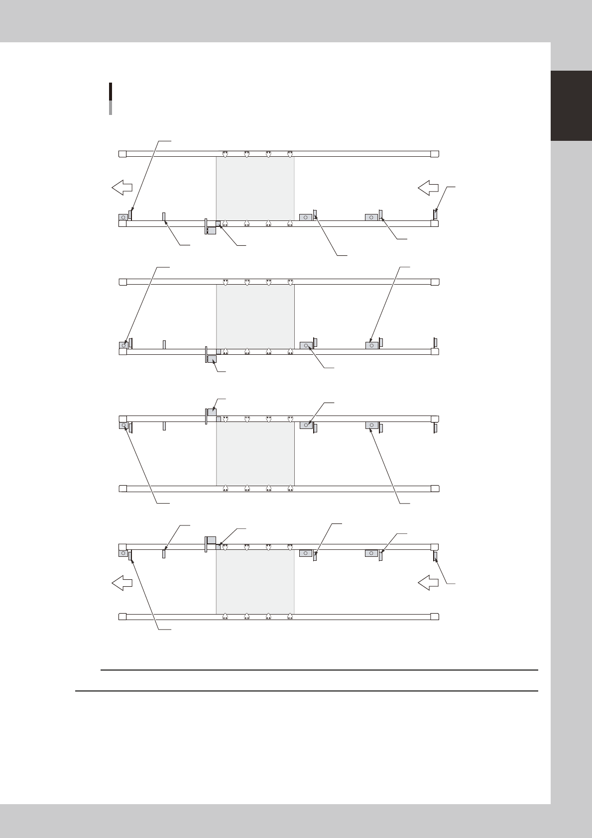
Single-lane/Dual-lane
Sensor layout
N Lane 1
N Lane 2
Entrance sensor
N 01008C 5
Exit sensor
N 01008D3
Standby position sensor 1
N 01008C 0
Standby position sensor 2
N 01008C 7
Board sensor 1 of component
mounting N 01008C1
WorkOut
N0100903
Exit stopper
with no sensor
Standby position stopper 1
N 01008C3
Standby position stopper 2
N 01008E4
Stopper of component 1
N 01008D5
Entrance sensor
N01008C6
Exit sensor
N01008D4
Standby position sensor 1
N01008D0
Standby position sensor 2
N01008E1
Board sensor 1 of component
mounting N01008D1
WorkOut
N0100917
Exit stopper
with no sensor
Standby position stopper 1
N01008C4
Standby position stopper 2
N01008E5
Stopper of component 1
N01008D7
23115-L4-10
n
NOTE
Only Lane 1 applies to single-lane machines.
1-22
1
Part names and functions
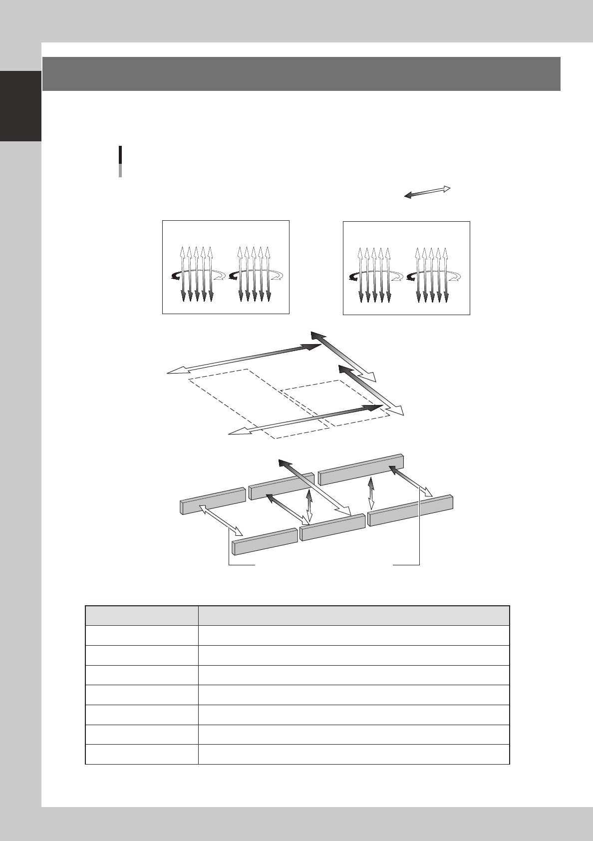
6. Axis configuration
The machine axis configuration and operation are shown in the drawing and table below.
n
Dual-stage
Plus direction
Minus direction
YB axis
Stage 2
Stage 1
YA axis
XA axis
XB axis
U2 axis
W1 axis
(W1 axis)
W2 axis
Axis configuration
Example of RL (Right-to-left flow) when viewed from the front of the machine
RA1 axis
RB1 axis
RA2 axis
RB2 axis
N Head axes
N Main axes
N Transfer axes
A table Head unit
B table Head unit
ZB1ZB10 ZB6 ZB5
ZA10ZA1 ZA5 ZA6
PU1 axis
PU2
axis
These axes are interlocked with each other.
23116-L4-00
n
Function of each axis
Axis Function
XA, XB Moves the head assembly above the table in parallel with the board flow on the conveyor.
YA, YB Moves the head assembly perpendicular to the board flow on the conveyor.
U2 Moves the conveyor (W2) in the Y axis direction.
RA1, RA2, RB1, RB2 Rotates the nozzle shaft of each head.
ZA1 to ZA10, ZB1 to ZB10 Moves the component pick-and-place head of each head vertically.
W1, W2 Changes the conveyor width.
PU1, PU2 Moves the push-up plate vertically.