YS24X_Ope_E.pdf - 第60页
1-23 1 Part names and functions n Single-lane Plus direction Minus direction YB axis Y A axis XA axis XB axis W1 axis Axis configuration Example of RL (Right-to-left flow) when viewed from the front of the machine RA1 ax…
1-22
1
Part names and functions
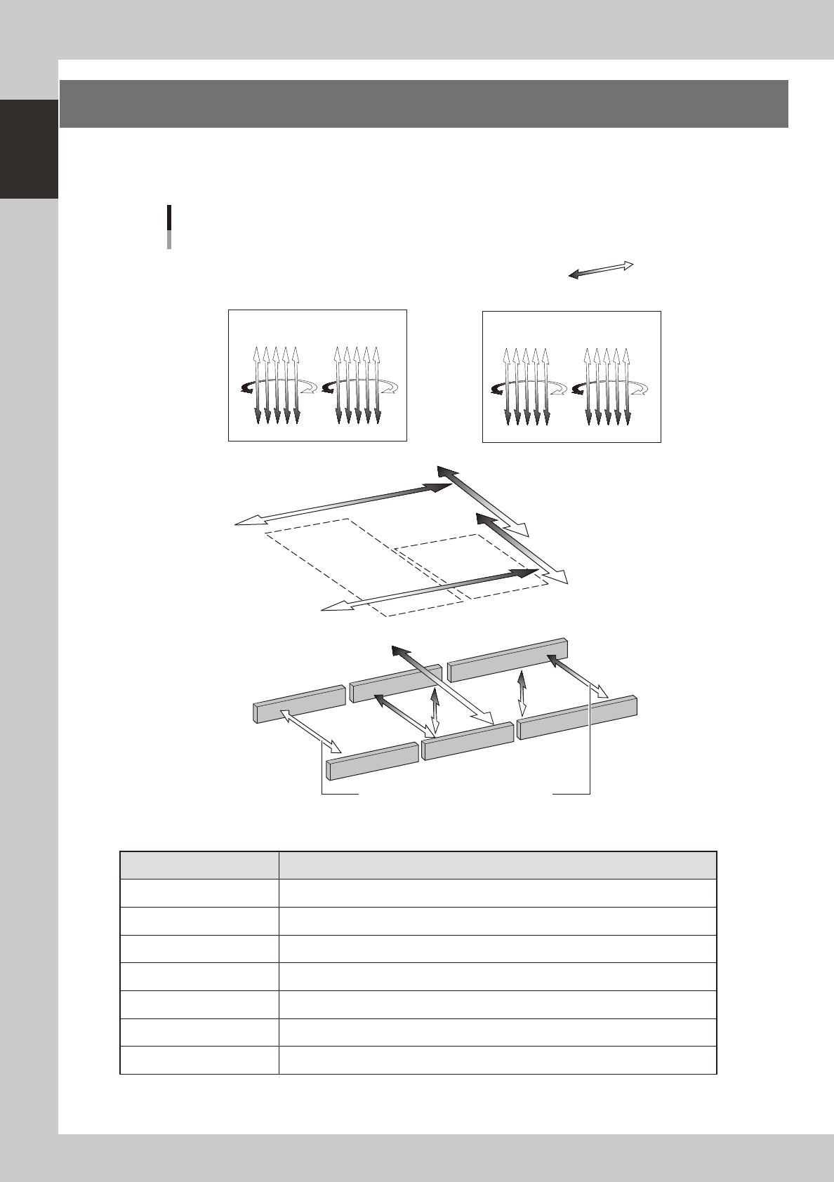
6. Axis configuration
The machine axis configuration and operation are shown in the drawing and table below.
n
Dual-stage
Plus direction
Minus direction
YB axis
Stage 2
Stage 1
YA axis
XA axis
XB axis
U2 axis
W1 axis
(W1 axis)
W2 axis
Axis configuration
Example of RL (Right-to-left flow) when viewed from the front of the machine
RA1 axis
RB1 axis
RA2 axis
RB2 axis
N Head axes
N Main axes
N Transfer axes
A table Head unit
B table Head unit
ZB1ZB10 ZB6 ZB5
ZA10ZA1 ZA5 ZA6
PU1 axis
PU2
axis
These axes are interlocked with each other.
23116-L4-00
n
Function of each axis
Axis Function
XA, XB Moves the head assembly above the table in parallel with the board flow on the conveyor.
YA, YB Moves the head assembly perpendicular to the board flow on the conveyor.
U2 Moves the conveyor (W2) in the Y axis direction.
RA1, RA2, RB1, RB2 Rotates the nozzle shaft of each head.
ZA1 to ZA10, ZB1 to ZB10 Moves the component pick-and-place head of each head vertically.
W1, W2 Changes the conveyor width.
PU1, PU2 Moves the push-up plate vertically.
1-23
1
Part names and functions
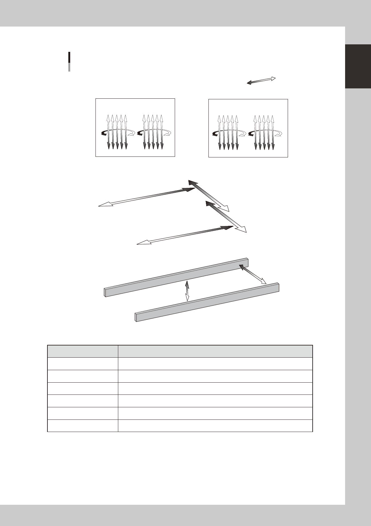
n
Single-lane
Plus direction
Minus direction
YB axis
YA axis
XA axis
XB axis
W1 axis
Axis configuration
Example of RL (Right-to-left flow) when viewed from the front of the machine
RA1 axis
RB1 axis
RA2 axis
RB2 axis
N Head axes
N Main axes
N Transfer axes
A table Head unit
B table Head unit
ZB1ZB10 ZB6 ZB5
ZA10ZA1 ZA5 ZA6
PU axis
23117-L4-00
n
Function of each axis
Axis Function
XA, XB Moves the head assembly above the table in parallel with the board flow on the conveyor.
YA, YB Moves the head assembly perpendicular to the board flow on the conveyor.
RA1, RA2, RB1, RB2 Rotates the nozzle shaft of each head.
ZA1 to ZA10, ZB1 to ZB10 Moves the component pick-and-place head of each head vertically.
W Changes the conveyor width.
PU Moves the push-up plate vertically.
1-24
1
Part names and functions
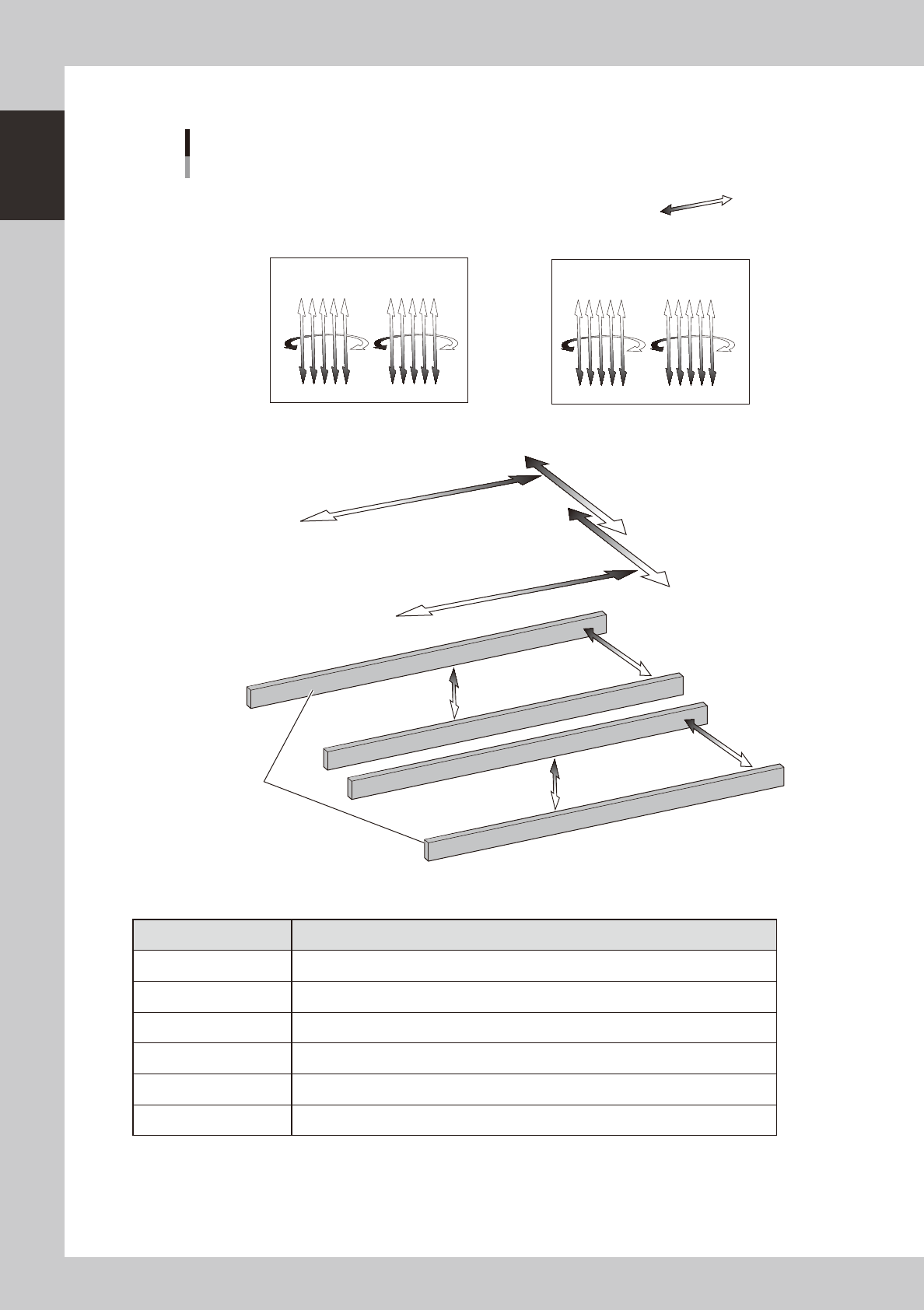
n
Dual-lane
Plus direction
Minus direction
W2 axis
Axis configuration
Example of RL (Right-to-left flow) when viewed from the front of the machine
RA1 axis
RB1 axis
RA2 axis
RB2 axis
N Head axes
N Main axes
A table Head unit
B table Head unit
ZB1ZB10 ZB6 ZB5
ZA10ZA1 ZA5 ZA6
Fixed
conveyor rail
Lane 1
Lane 2
W1 axis
PU1 axis
PU2 axis
YB axis
YA axis
XA axis
XB axis
N Transfer axes
23133-L4-00
n
Function of each axis
Axis Function
XA, XB Moves the head assembly above the table in parallel with the board flow on the conveyor.
YA, YB Moves the head assembly perpendicular to the board flow on the conveyor.
RA1, RA2, RB1, RB2 Rotates the nozzle shaft of each head.
ZA1 to ZA10, ZB1 to ZB10 Moves the component pick-and-place head of each head vertically.
W1, W2 Changes the conveyor width.
PU1, PU2 Moves the push-up plate vertically.