YS24X_Ope_E.pdf - 第67页
1-30 1 Part names and functions 3 A confirmation dialog box appears asking y ou to make a final check. Check the contents of the dialog box and pr ess the corresponding button. [OK] : Perfor ms nozzle shaft blow to clean…
1-29
1
Part names and functions
n
When the machine has a nozzle station (option)
When the settings are made so that all nozzles can be changed using a nozzle station (option), follow these steps.
1
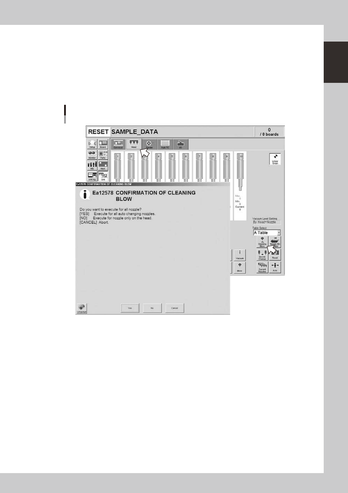
Open the [Unit] – [Head] screen.
2
Press the [Cleaning Blow] button.
A confirmation dialog box appears asking whether to perform nozzle shaft blow.
Press the [OK] button to perform nozzle shaft blow and proceed to the next step. If you want to cancel
nozzle shaft blow, press the [Cancel] button.
Nozzle shaft blow
When nozzle station (option) is used
24103-L4-00
1-30
1
Part names and functions
3
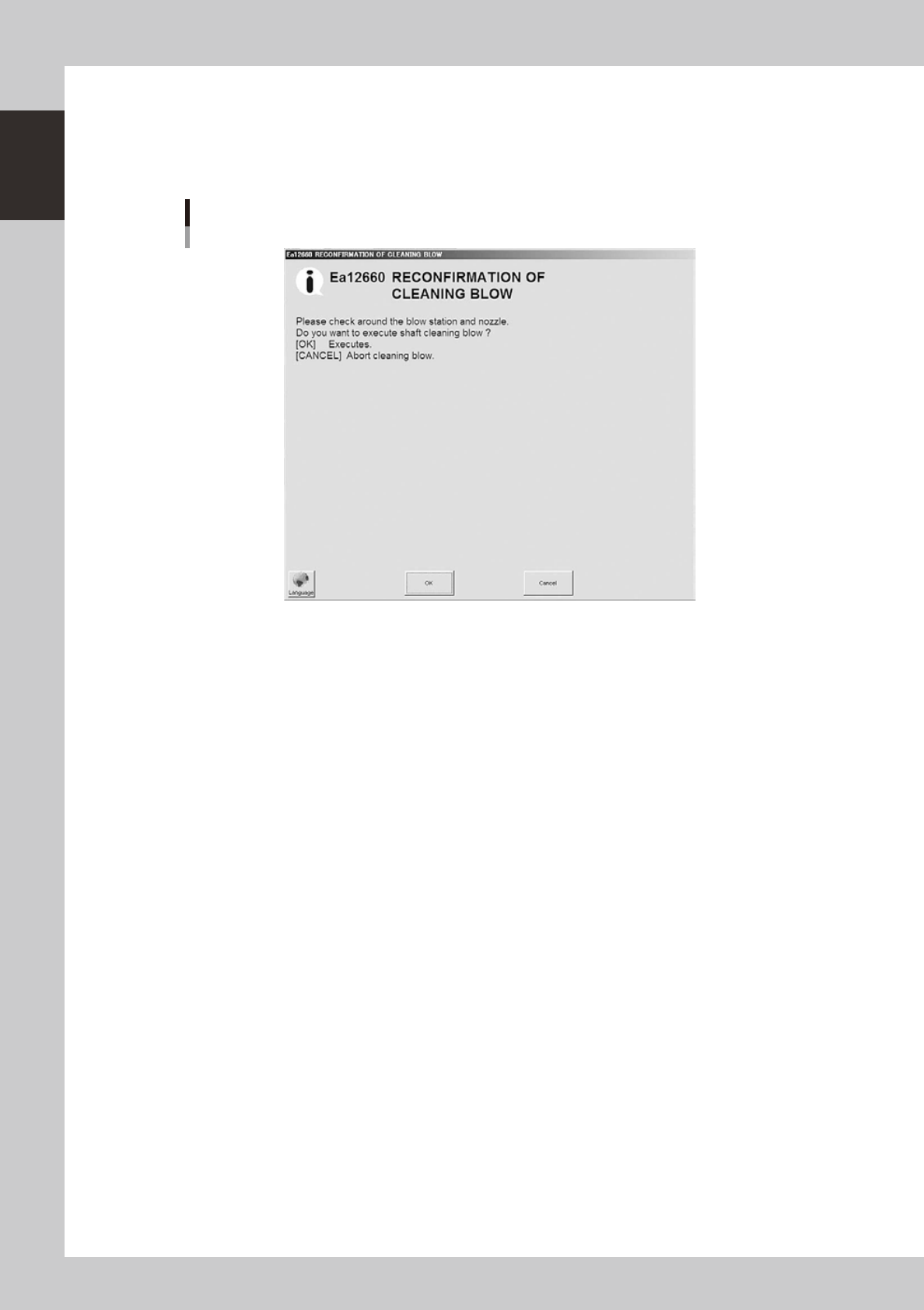
A confirmation dialog box appears asking you to make a final check.
Check the contents of the dialog box and press the corresponding button.
[OK] : Performs nozzle shaft blow to clean the nozzles.
[CANCEL] :
Closes the dialog box and returns to the [Unit]-[Head] screen without performing nozzle shaft blow.
Final confirmation dialog box for nozzle shaft blow
24104-L4-00
n
Safety checks
The nozzle shaft blow function also contains the following safety checks.
• Nozzle shaft blow interruption alarm
The head immediately rises if operation stops during nozzle shaft blow due to emergency stop or an interlock triggering.
If the head rises but the air blow still continues, then the nozzle might come loose from the head. To prevent this, a
confirmation dialog box appears if the machine operation stopped during nozzle shaft blow.
• Nozzle sensors to check whether a nozzle is left on the blow station
The nozzle shaft blow function forces high-pressure air through the nozzles during cleaning, so the nozzles might come
loose from the head if machine operation stops during nozzle blow. If a nozzle comes loose from the head and remains
on the blow station while the automatic operation still continues, then the nozzle left on the blow station might interfere
with other heads or with the multi-max unit. To prevent this, nozzle sensors are installed so that the machine constantly
monitors whether a nozzle is left on the blow station.
An “interlock error” is issued if any of these sensors detects a nozzle on the blow station at any time other than when the
head is lowered during nozzle blow. The machine operation is then disabled.

1-31
1
Part names and functions
8. Tape cutter (option)
Tape cutters are internally installed as options for the YS series. There are two types of tape cutting during
automatic operation. Both types can be jointly used.
Tape cutting is available in the following two types:
• During component mounting : Tape is cut during component mounting after completion of pickup.
• During board conveying : Tape is cut while each board is conveyed to exit after component mounting.
n
Tape cutter open/close timing
• Return to origin (close
→
open)
Opens all tape cutters immediately after return-to-origin operation.
• During start and reset of automatic operation (close
→
open)
Closes all tape cutters and then opens them.
• During machine power-off (open
→
close)
When turning off the machine power, a confirmation dialog box appears to help navigate the processing method. Pressing
the OK button closes all tape cutters.
8.1 Tape cutting during component mounting
Tape is cut during component mounting based on the actual feed length (tape feed length) that the tape is fed
from the feeder.
• Tape feed length
This is the length calculated for each feeder from the feed pitch and the tape feed count of the components during
component pickup. Tape cut length is decided during component mounting based on the longest tape length fed into one
cutter.
• Feed pitch
Feed pitch is calculated using the feed pitch set (in memory) for the SS feeder at each station, or the feed pitch set in the
board data.
• Tape cut timing
Tape is cut after component recognition during the mounting operation.
However, no component is mounted if the tape cutting has not finished before feeding of the next component group for
pickup starts.
• Tape cutting conditions
Tape must be cut during component mounting, in the period from "Standard cut length" to "Maximum cut length" that
were preset in the machine settings.
1. Tape is always cut when tape feed length exceeds maximum cut length.
2. Tape is usually cut when tape feed length exceeds the standard cut length.
n
NOTE
Tape feed length being counted when tape cutting ends normally is reset.
n
Delaying the tape cutting
• If feeders on multiple tape cutters are simultaneously longer than the standard cut length and shorter than the
maximum cut length, then the tape with longer feed lengths are cut, and cutting of tape with shorter feed lengths is
delayed.
• Even if longer than the standard cut length, the tape cutting is delayed to allow component mounting to proceed in
cases where the number of heads used in this pickup group is fewer than the specified number of heads.