YS24X_Ope_E.pdf - 第70页
1-33 1 Part names and functions 9. Other options 9.1 Coplanarity checker T he coplanarity checker measures lead linearity and coplanarity of QFP/SOP leads or BGA bumps at high speeds, and determines "pass/fail"…

1-32
1
Part names and functions
8.2 Tape cutting during board conveying
All tape cutters can operate with no special restrictions while a board is being conveyed to the exit after
component mounting is completed.
However, if there has been no tape feed whatsoever in tape feeders installed on the rear feeder plate since the
last tape cutting, then the rear tape cutters will not operate.
• Tape cut timing
Tape cutting operates at the timing that the boards are unclamped and conveyed to the exit after component mounting is
completed.
• Tape cutting conditions
Tape cutting is performed each time a board is conveyed to the exit after completing component mounting, and tape
cutting starts on all tape cutters that are set enabled.
8.3 Restrictions (caution)
Conditions affecting component mounting time
• If the tape feed lengths on the front and rear tape cutters simultaneously exceed the maximum cut length, then the
machine might delay component mounting to allow each tape cutter to cut the tape alternately.
• If the tape cutting speed drops due to a breakdown such as in the tape cutter valves or cylinder, then the machine
might delay component mounting.
Cautions for tape cutting during board conveying
Use caution when using board data where there is a large component feed length per feeder for each board, since the
tape that was cut off might hang up on the tape eject slot and does not reach the trash box.
Setting the standard cut length and maximum cut length
Hangs ups tend to occur during tape cutting performed during component mounting if the standard cut length and
maximum cut length were set to a large figure. Set these to a shorter figure if the tape does not easily eject after tape
cutting.
As a general guide, set the the standard cut length to 80mm, and the maximum cut length to 120mm.
n
NOTE
Operation buttons will be disabled during emergency stop or if an interlock is triggered.
1-33
1
Part names and functions
9. Other options
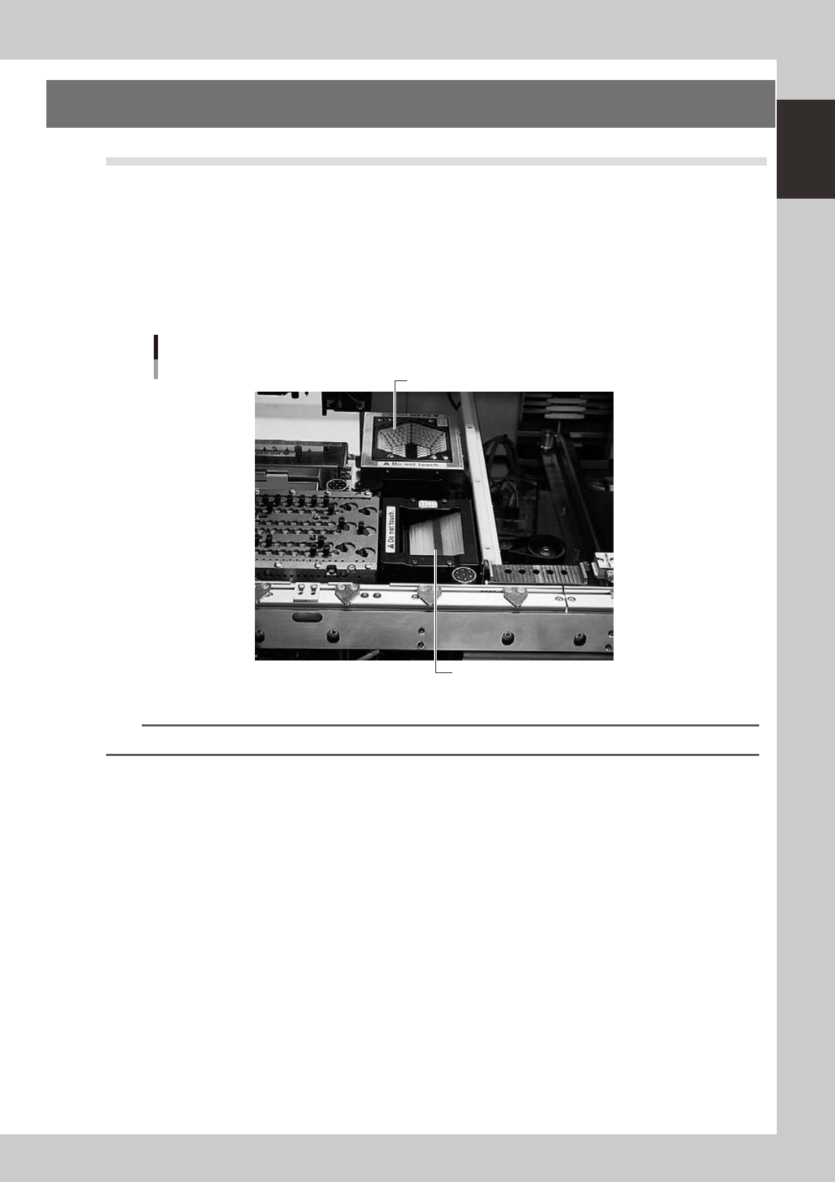
9.1 Coplanarity checker
The coplanarity checker measures lead linearity and coplanarity of QFP/SOP leads or BGA bumps at high
speeds, and determines "pass/fail".
The coplanarity checker has the following two functions:
• Coplanarity check
Inspects uniformity of the lead bottom against the seating plane of components having wire leads or solder balls.
• Component recognition height check
Prevents lead components from being mounted in an inverted position.
Coplanarity checker
Multi-vision camera (standard)
Coplanarity checker
23128-L4-00
n
NOTE
For instructions on how to use the coplanarity checker, refer to the YS series programming manual.
1-34
1
Part names and functions
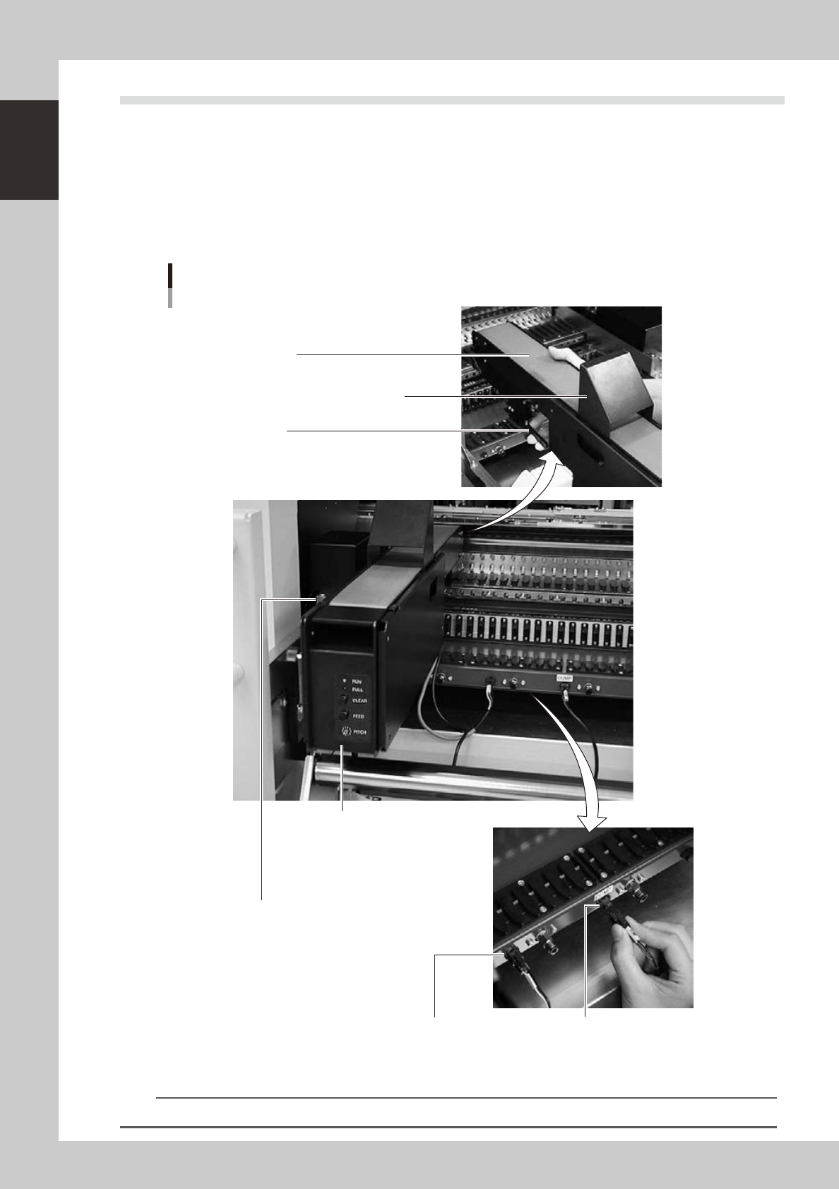
9.2 QFP dump station
The QFP dump station (hereafter called dump station) is a QFP recovery conveyor designed to attach to the
feeder plate of a YAMAHA surface mounter. If a QFP is judged defective by vision camera recognition, that
QFP is temporarily placed on this dump station without being damaged. The QFP placed on the dump station
is then conveyed back at a specified feed pitch. When the dump station becomes full, the memory counter or
overflow sensor detects it and displays an error message before the next defective QFP is returned to the dump
station.
Photographs below show major parts and functions of the dump station.
Clamp lever
Use this lever to lock or unlock the dump station to
the feeder plate.
DUMP harness (signal cable)
Used to interface between the dump station
and the mounter for exchanging signals.
FEEDER harness (power supply cable)
Supplies power to the dump station from
the mounter.
Manual operation panel
Use the switches on this operation panel
to set the feed pitch, move the belt at the
specified pitch and clear the count.
The LED lamps also show the
operation status.
Overflow sensor (option)
QFPs placed on the dump station
are carried back by the belt conveyor.
When a QFP arrives at the end of
the dump station, this overflow sensor
detects it and displays an error message.
Conveyor belt
Conveys QFPs placed on the dump station at a
specified feed pitch.
Safety cover
Major parts and functions
23129-L4-00
n
NOTE
For how to use the QFP dump station, refer to the option manual "QFP dump station".