YS24X_Ope_E.pdf - 第71页
1-34 1 Part names and functions 9.2 QFP dump station T he QFP dump station (hereafter called dump station) is a QFP recovery convey or designed to attach to the feeder plate of a Y AMAHA surface mounter . If a QFP is jud…
1-33
1
Part names and functions
9. Other options
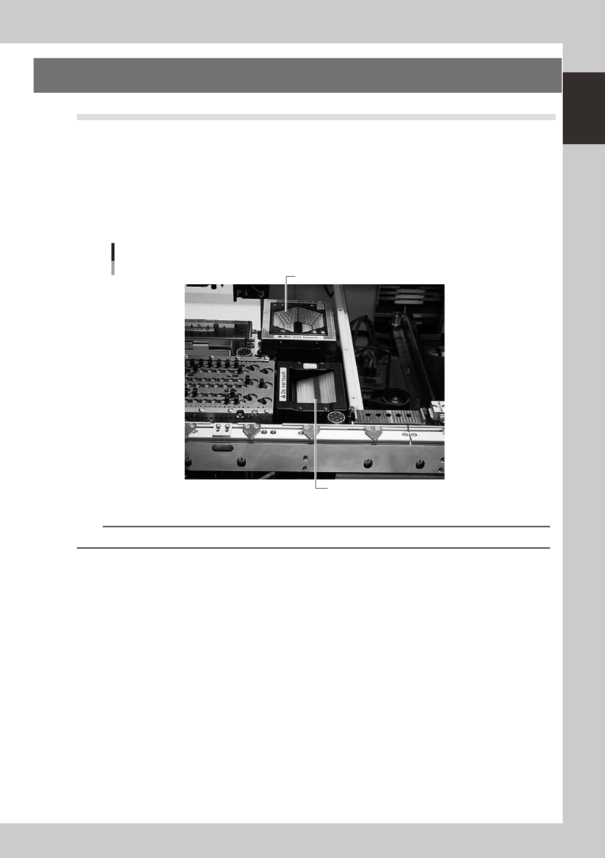
9.1 Coplanarity checker
The coplanarity checker measures lead linearity and coplanarity of QFP/SOP leads or BGA bumps at high
speeds, and determines "pass/fail".
The coplanarity checker has the following two functions:
• Coplanarity check
Inspects uniformity of the lead bottom against the seating plane of components having wire leads or solder balls.
• Component recognition height check
Prevents lead components from being mounted in an inverted position.
Coplanarity checker
Multi-vision camera (standard)
Coplanarity checker
23128-L4-00
n
NOTE
For instructions on how to use the coplanarity checker, refer to the YS series programming manual.
1-34
1
Part names and functions
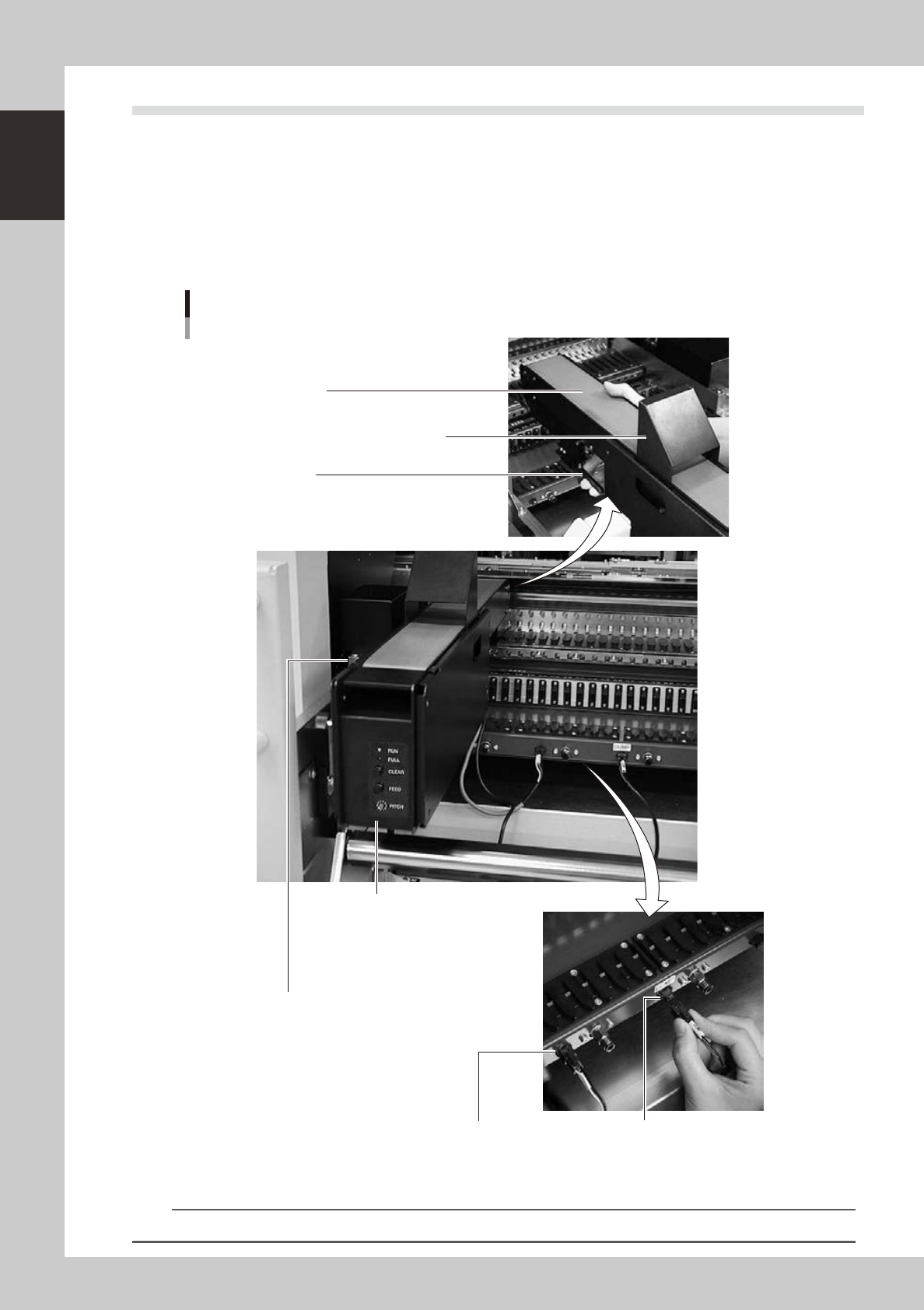
9.2 QFP dump station
The QFP dump station (hereafter called dump station) is a QFP recovery conveyor designed to attach to the
feeder plate of a YAMAHA surface mounter. If a QFP is judged defective by vision camera recognition, that
QFP is temporarily placed on this dump station without being damaged. The QFP placed on the dump station
is then conveyed back at a specified feed pitch. When the dump station becomes full, the memory counter or
overflow sensor detects it and displays an error message before the next defective QFP is returned to the dump
station.
Photographs below show major parts and functions of the dump station.
Clamp lever
Use this lever to lock or unlock the dump station to
the feeder plate.
DUMP harness (signal cable)
Used to interface between the dump station
and the mounter for exchanging signals.
FEEDER harness (power supply cable)
Supplies power to the dump station from
the mounter.
Manual operation panel
Use the switches on this operation panel
to set the feed pitch, move the belt at the
specified pitch and clear the count.
The LED lamps also show the
operation status.
Overflow sensor (option)
QFPs placed on the dump station
are carried back by the belt conveyor.
When a QFP arrives at the end of
the dump station, this overflow sensor
detects it and displays an error message.
Conveyor belt
Conveys QFPs placed on the dump station at a
specified feed pitch.
Safety cover
Major parts and functions
23129-L4-00
n
NOTE
For how to use the QFP dump station, refer to the option manual "QFP dump station".
1-35
1
Part names and functions
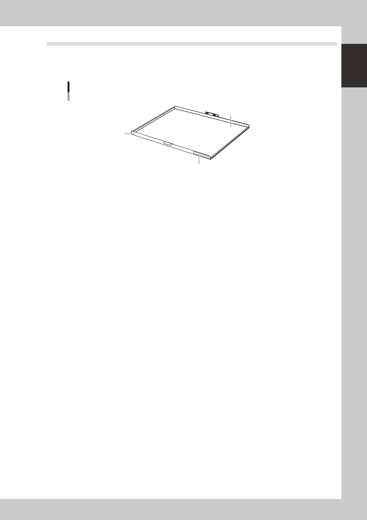
9.3 Recovery pallet
The recovery pallet retrieves defective parts detected by the recognition camera without damaging them. The
recovery pallet is set at a specified position in the sATS
II
(called sATS from now on) and is used exclusively to
collect the defective parts.
Recovery pallet
Sticky transparent sheet
is attached here
Higher than on
standard pallet
Yellow sticker (front and rear)
23132-L4-00
n
Recovery pallet position
• The recovery pallet position is set in the 15th shelf of magazine 1 (or in the 30th shelf if magazine 2) as the default
position when shipped from the factory. You can shift this position to where needed by changing the machine setting.
• A yellow sticker is attached to the recovery pallet to help identify it from other pallets. Before starting work, open the
sATS door and make sure that the pallet with the yellow sticker is placed in its specified position.
n
Operating limits
• The recovery pallet is only used on the B table. If the A table stops operating due to some problem, then the disposal
position or disposal station serves as the recovery point.
• Parts are only discarded into the recovery pallet during automatic operation. During adjust mode or reset operation,
the parts are discarded into the disposal position (dump box) even if “Recovery Unit” was specified in the data.
n
Part sizes
• Maximum part sizes (XY) the recovery pallet can handle are set in the machine data. Maximum part sizes usable by the
machine are already set as default values.
• Part heights up to 8.5mm can be stored to a pallet pitch of 12.5mm, and to 15mm at a pallet pitch of 25mm.
The spacing between parts and the number of parts that can be placed in the recovery pallet are automatically calculated
from the maximum size. Parts are placed at an equal spacing regardless of their size. If you want to change the maximum
number of parts to be placed in the recovery pallet, you must change the maximum part size (XY) in the machine
settings.
n
Parts requiring special precautions during recovery
• Parts such as transformers, PGA, EPROMS and quartz oscillators might shift around on the pallet surface.
• Parts whose center of gravity is higher than the edge of the pallet might drop off the pallet if they are moved.
• Parts that have only a small contact surface with the sticky pallet surface or parts having irregular contact surfaces
such as aluminum capacitors might shift around on the pallet surface.
• Wafers or similar parts having an even, flat surface making close contact with the adhesive surface on the pallet might
be damaged when peeled from the pallet due to the adhesive force.