YS24X_Ope_E.pdf - 第85页
2-10 2 asic operation About error screen Error screen Mark detection error 1 2 3 7 4 6 5 [Error Switching] button 24202-L4-00 1. Error count display Shows the currently displa yed error and the total number of errors. …
2-9
2
asic operation
n
Various buttons and parameter input boxes
Various types of buttons, selection tabs and parameter input boxes are used on the operation screen.
1
1
2
3
4
5
6
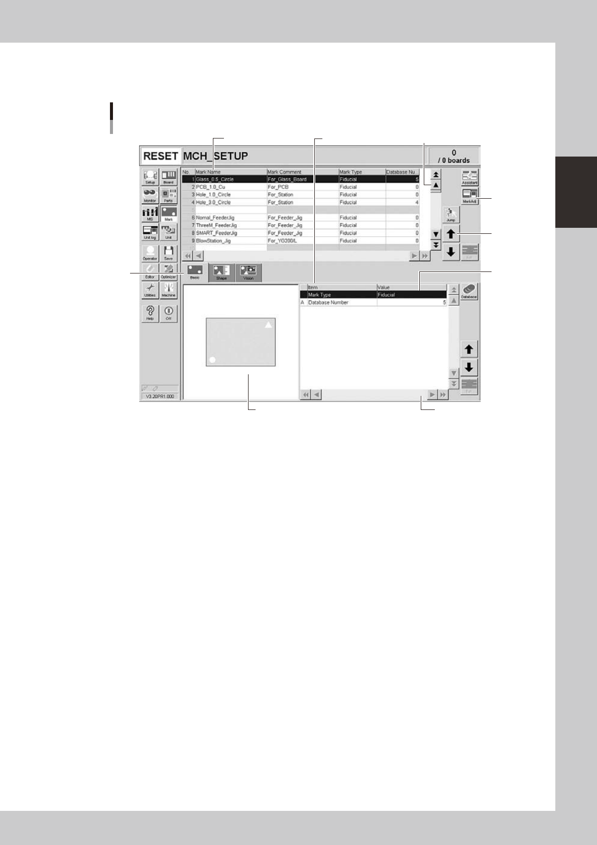
Operation screen basic elements
Mark screen
Parameter listData No. list
24201-L4-00
1. Scroll bar and button (up/down, left/right)
Use the scroll bars or arrow buttons to see hidden items in the data No. list or parameter list.
2. Operation button
Press these buttons to open the next operation screen or dialog box.
3. Line up/down button
Use these buttons to move the cursor up or down through the data No. list or parameter list.
4. Parameter input box
Select, enter or edit parameters here. When the keyboard is used, double-click on a parameter input box to enter or edit
the data.
When a touch screen (option) is used, press the [Edit] button on the lower right of the parameter list. The edit box then
pops up for data input and editing.
5. Selection tab
Select this tab to switch the parameter input screen.
6. Assistant screen
Shows an illustration or information useful for parameter input or editing.
Alphabet characters shown in the parameter list and in the illustration on this screen correspond to each other.
Lane select button (dual-lane machines)
This button is displayed when producing boards using both lanes of dual-lane machines. Use this button to select the
lane to be displayed on the operation screen.
2-10
2
asic operation
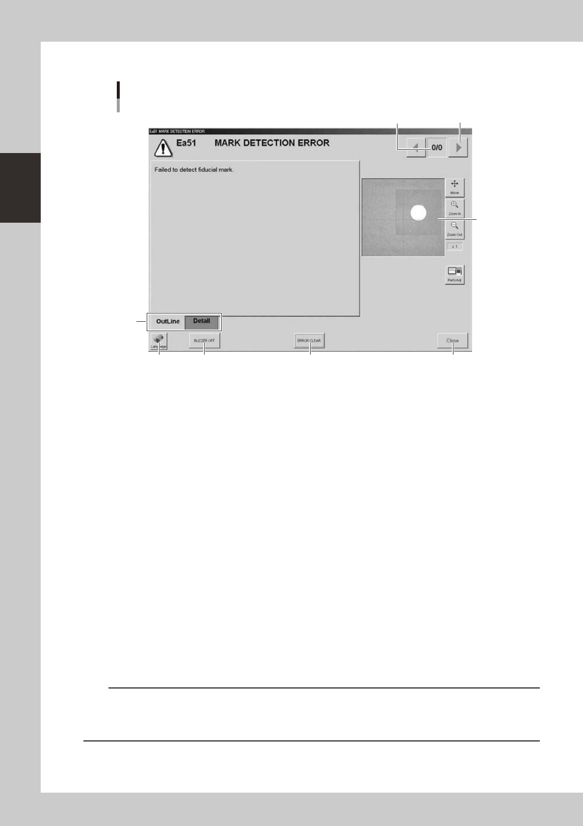
About error screen
Error screen
Mark detection error
1
2
3
7
46 5
[Error Switching] button
24202-L4-00
1. Error count display
Shows the currently displayed error and the total number of errors. If two or more errors occurred, use the [Error
Switching] buttons (right/left arrow buttons) to switch to other error screens.
2. Message switching tab
Outline:
Displays a message for the operator.
Detail:
Displays a message for the administrator/supervisor or service personnel. This tab does not appear unless a message is
available.
3. Recognition image display (component pickup error and mark recognition error screens)
If an error has occurred in image processing during component pickup or mark recognition, the error image is displayed
here.
4. [BUZZER OFF]
Turns off the buzzer.
5. [ERROR CLEAR]
Clears the error that has occurred.
6. [Language] button
Switches the language of the message displayed on the error screen.
7. [Close] button
Closes the error screen without clearing the error.
TIP
After closing the error screen by pressing the [Close] button, you can check the locations where errors have occurred
by opening the [Monitor] - [Production] tab. Pressing the [Error Detail] button on the [Production] tab screen redisplays
the error message. For more details on the [Production] tab screen, refer to Chapter 3, "Starting and ending
production".
2-11
2
asic operation
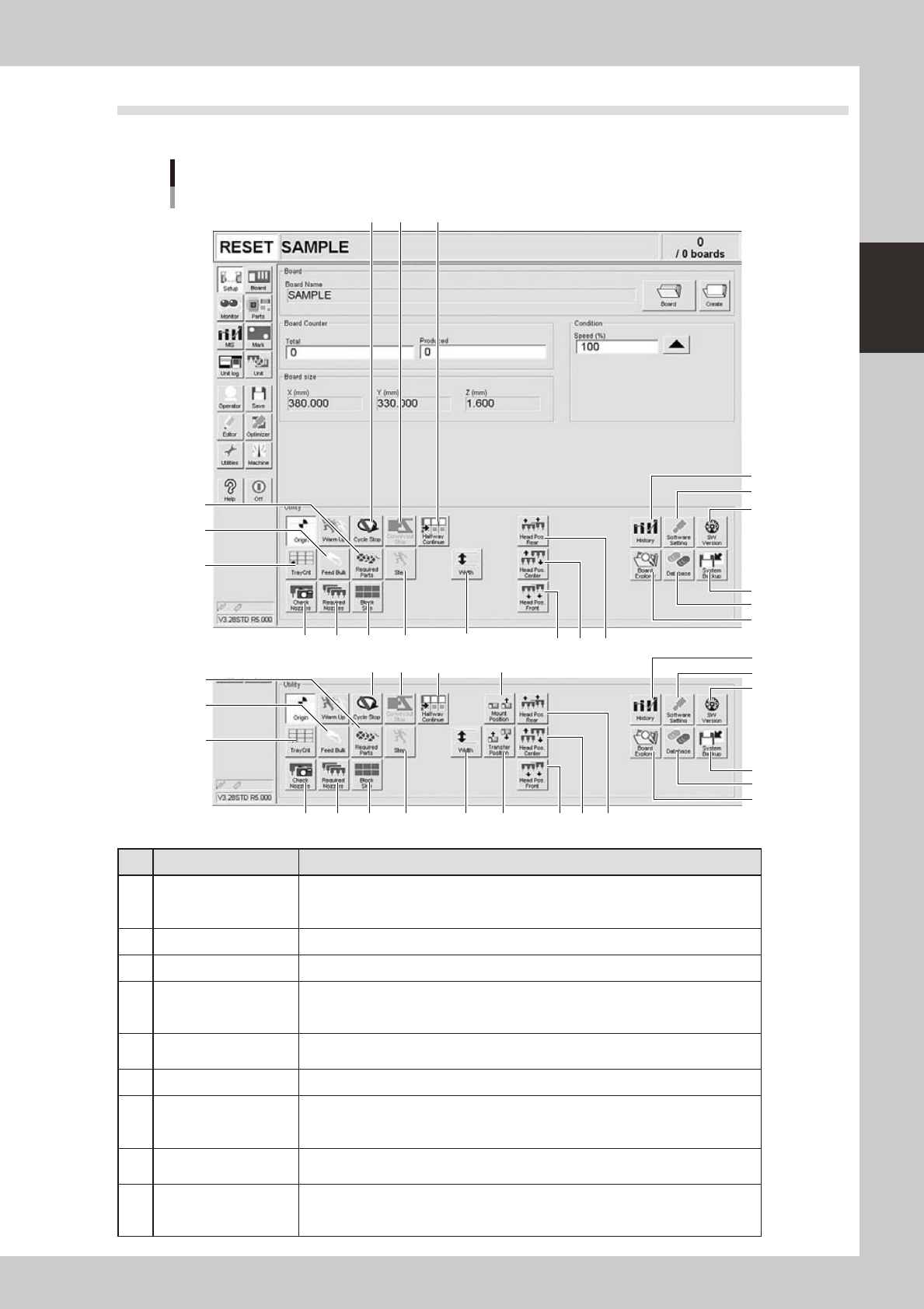
2.2 Setup screen
This section describes the operation buttons displayed on the Setup screen.
Setup screen
1
2
3
4
5
6
7 8 9
10
11
1614
13
12
22
22
18 19 20 21
17
15
1
2
3
4
5
6
7 8 9
10
11
1614
13
12
19 20 21
15
NSingle-lane / Dual-lane
NDual-stage
24203-L4-20
Button name Function
1 History
Saves production history data, and saves or clear any desired items of "MIS" and
"Unit log" records. Also use this button when removing a storage medium from the
machine.
2 Software Setting Sets machine screen display items, adds or deletes operators, and sets passwords.
3 Version Shows version information on application software and system.
4 System Backup
Makes a backup of machine coordinates, accuracy information, option device
information and standard coordinates necessary for machine operation or restores
the data using the backup.
5 Database
Makes a backup of parts and mark database necessary for board production or
restores the data using the backup. Also sets the database locations.
6 Board Explorer Moves, backs up, restores or copies board data.
7 Cycle Stop
Stops machine operation just after mounting components on the current board, for
example, to check the mounted results or to prevent the board from flowing to the
downstream machine.
8 Convey-out Stop
Stops machine operation after mounting components on all boards on the conveyor
and transferring them to the downstream machine.
9 Halfway Continue
After stopping the machine for some reason during component mounting and
resetting the data, pressing this button loads that data to resume component
mounting from the next mount point.