YS24X_Ope_E.pdf - 第87页
2-12 2 asic operation Button name Function 10 Step T emporarily stops the machine at a specific position, for example, during initial component mounting, test mounting, or trouble analysis. 11 Required Parts Displays t…
2-11
2
asic operation
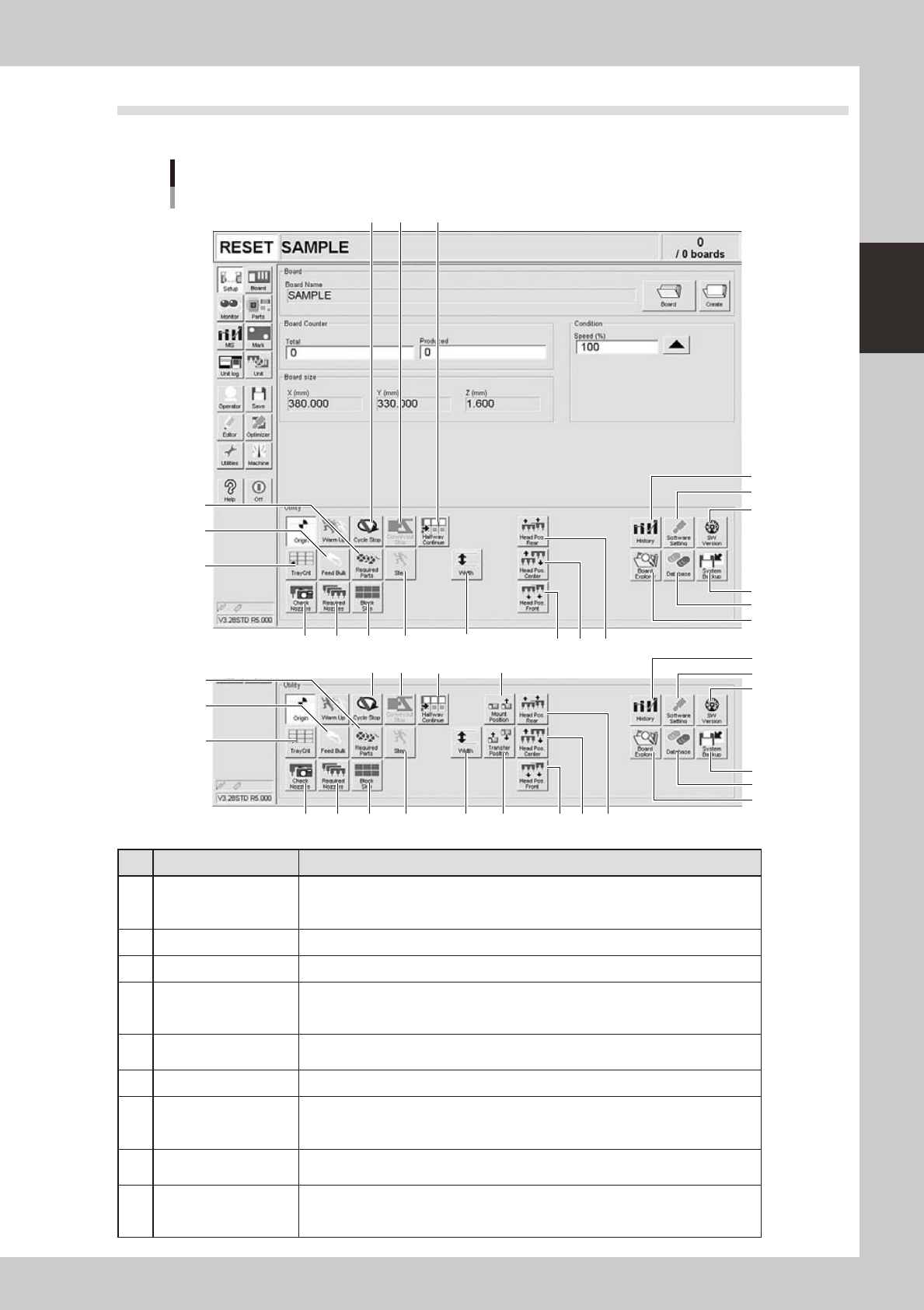
2.2 Setup screen
This section describes the operation buttons displayed on the Setup screen.
Setup screen
1
2
3
4
5
6
7 8 9
10
11
1614
13
12
22
22
18 19 20 21
17
15
1
2
3
4
5
6
7 8 9
10
11
1614
13
12
19 20 21
15
NSingle-lane / Dual-lane
NDual-stage
24203-L4-20
Button name Function
1 History
Saves production history data, and saves or clear any desired items of "MIS" and
"Unit log" records. Also use this button when removing a storage medium from the
machine.
2 Software Setting Sets machine screen display items, adds or deletes operators, and sets passwords.
3 Version Shows version information on application software and system.
4 System Backup
Makes a backup of machine coordinates, accuracy information, option device
information and standard coordinates necessary for machine operation or restores
the data using the backup.
5 Database
Makes a backup of parts and mark database necessary for board production or
restores the data using the backup. Also sets the database locations.
6 Board Explorer Moves, backs up, restores or copies board data.
7 Cycle Stop
Stops machine operation just after mounting components on the current board, for
example, to check the mounted results or to prevent the board from flowing to the
downstream machine.
8 Convey-out Stop
Stops machine operation after mounting components on all boards on the conveyor
and transferring them to the downstream machine.
9 Halfway Continue
After stopping the machine for some reason during component mounting and
resetting the data, pressing this button loads that data to resume component
mounting from the next mount point.
2-12
2
asic operation
Button name Function
10 Step
Temporarily stops the machine at a specific position, for example, during initial
component mounting, test mounting, or trouble analysis.
11 Required Parts
Displays the component types and feeder positions that are set up for the production
to be started.
In dual-lane machines, the component types and feeder positions on both lanes are
displayed.
12 Feed Bulk Not currently used.
13 Tray Cnt
Displays the number of tray components that have been used.(Single - lane / Dual -
lane+sATS
II
)
14 Check Nozzles
Checks if nozzle tips for chip components are dirty or clogged by acquiring their
images.
15 Required Nozzles Displays a list of nozzles to be used.
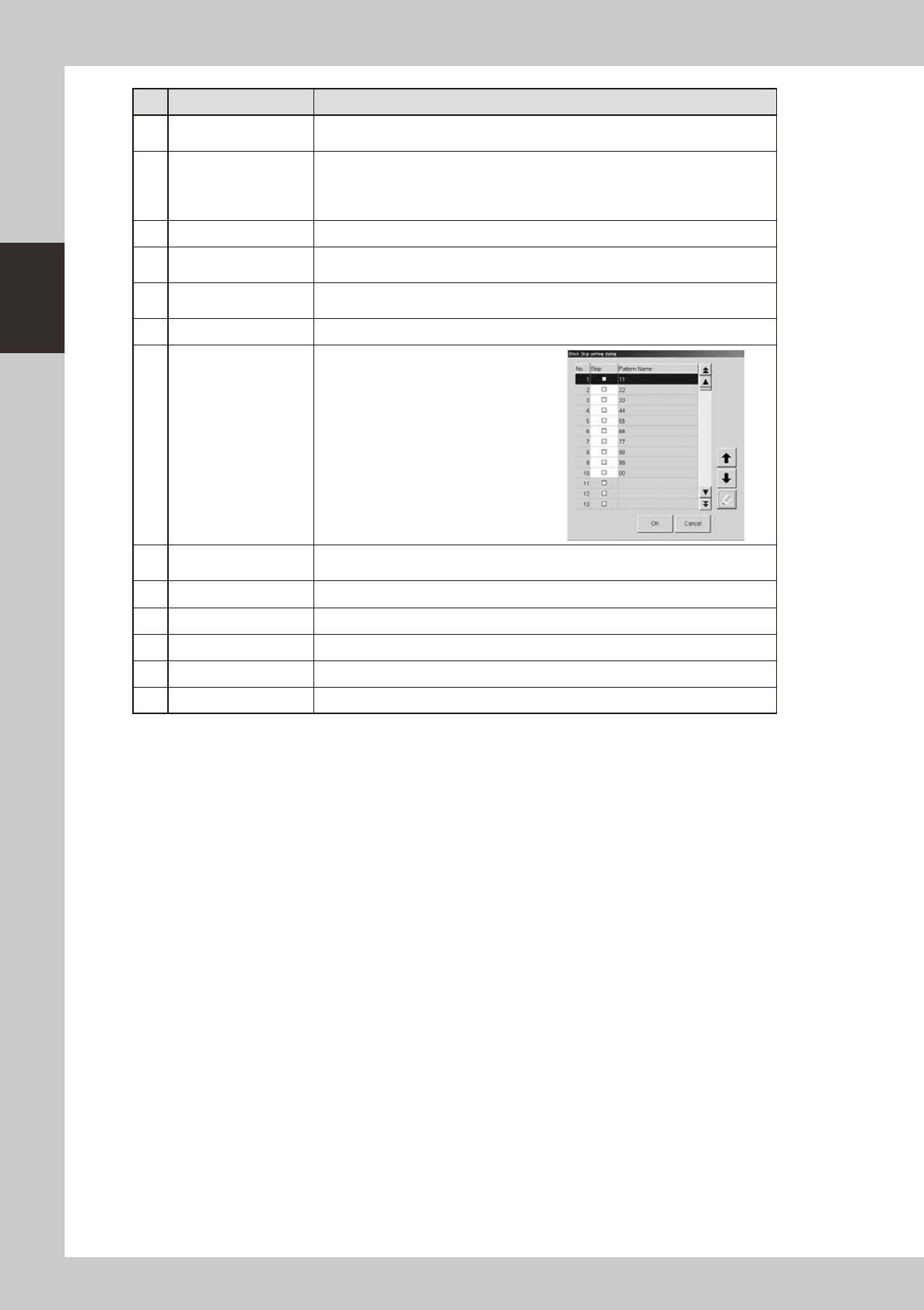
16 Block skip
This button becomes active when
board data with block distribution
performed is loaded.
Pressing this button displays the
"Block Skip Utility" dialog box that
allows you to set whether to skip
mounting components in each block.
17 Mount Position
Moves the conveyor to the component mounting position for the setup of the backup
pin. (dual-stage machines only)
18 Transfer Position Moves the conveyor to the transfer position when a board is carried in manually.
19 Head Pos. Front Moves both A and B heads to the front of the machine.
20 Head Pos. Center Moves both A and B heads to the center of the machine.
21 Head Pos. Rear Moves both A and B heads to the rear of the machine.
22 Width Changes the conveyor width.
2-13
2
asic operation
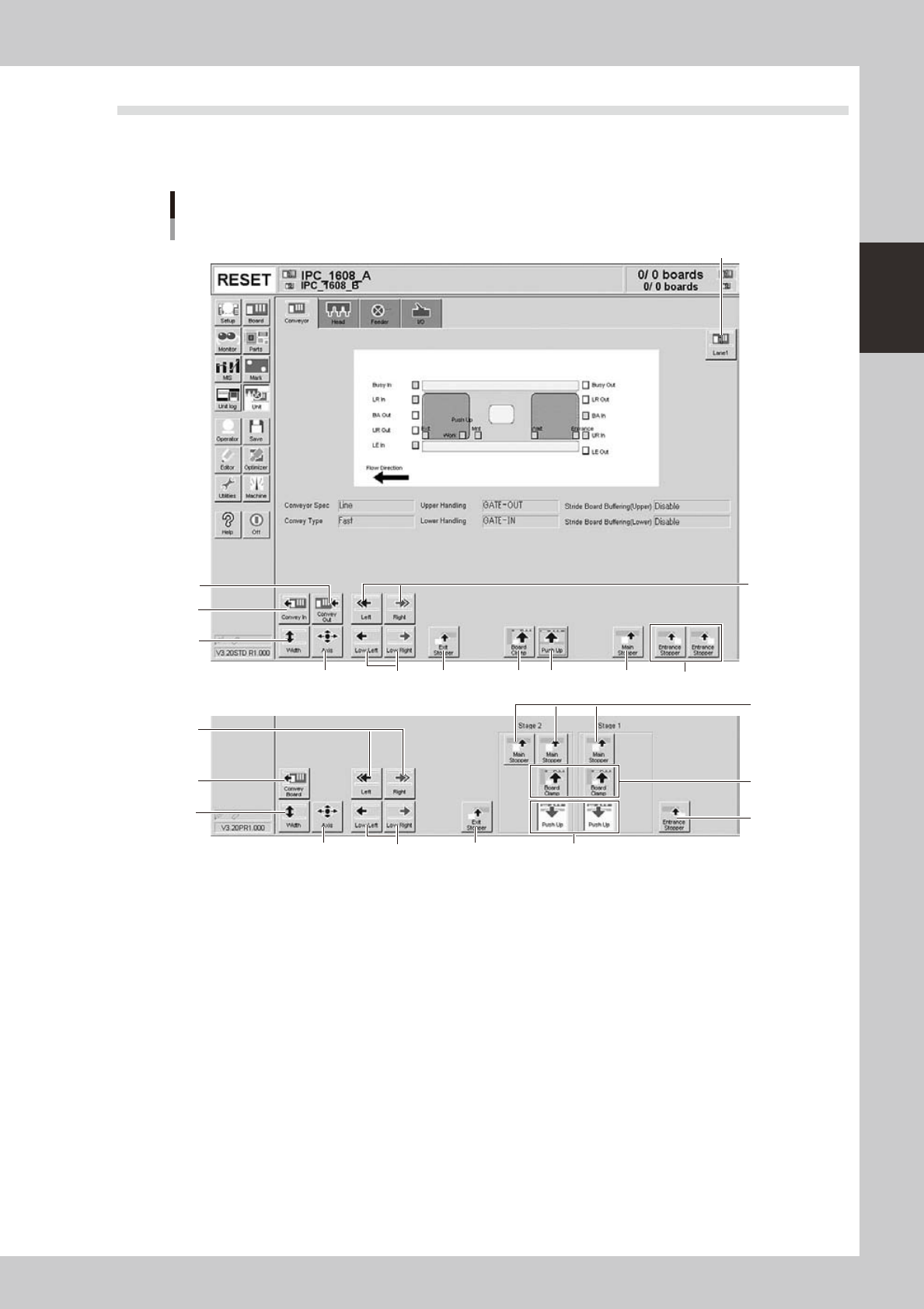
2.3 Unit screen
This section describes the manual operation buttons on the Unit screen.
n
Manual conveyor operation
Conveyor manual buttons
NSingle-lane / Dual-lane
NDual-stage
4
2
1
6
5
3
7
8 10 11 9 12
2
4
6
75
9
10
11
12
8
24204-L4-10
1. Lane select button (Dual-lane machines)
Switches the display between Lane 1 and Lane 2.
2. [Convey Board] button (Dual-stage), [Convey In] button (Single-lane / Dual-lane)
Moves the board from the conveyor entrance or standby position to the clamp position and clamps it.
3. [Convey Out] button (Single-lane / Dual-lane)
Unclamps the board and moves it to the exit stopper position.