YS24X_Ope_E.pdf - 第92页
2-17 2 asic operation n Manual feeder operation [Unit] – [Feeder] screen 1 4 7 8 2 6 9 5 3 24210-L4-10 Button name Function 1 Feed Each time pressing this button advances the tape at the specified pitch. 2 Back Each ti…
2-16
2
asic operation
n
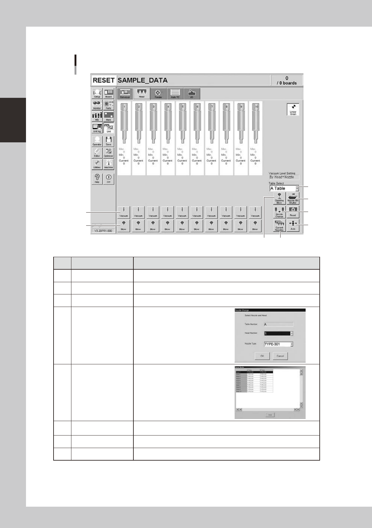
Manual head operation
[Unit] – [Head] screen
1
2
3
4
5
6
8
7
24207-L4-00
Button name Function
1 Vacuum Turns the vacuum of each head on or off.
2 Blow Turns the air blow in each head on or off.
3 Nozzle STN Shutter Opens or closes the nozzle station shutter.
4 Nozzle Change
Opens the "Nozzle Change" dialog box.
Specify the head and nozzle type to
perform nozzle change.
5 Current Nozzles
Shows a list of nozzle types currently
attached to each head.
6 Axis
Opens the "Move Axis" screen. This is the same as the [Axis] button on the [Unit]-
[Conveyor] screen.
7 Cleaning Blow Not currently used.
8 Table Select Switches between the A Table (front) and B Table (rear) displays.
2-17
2
asic operation
n
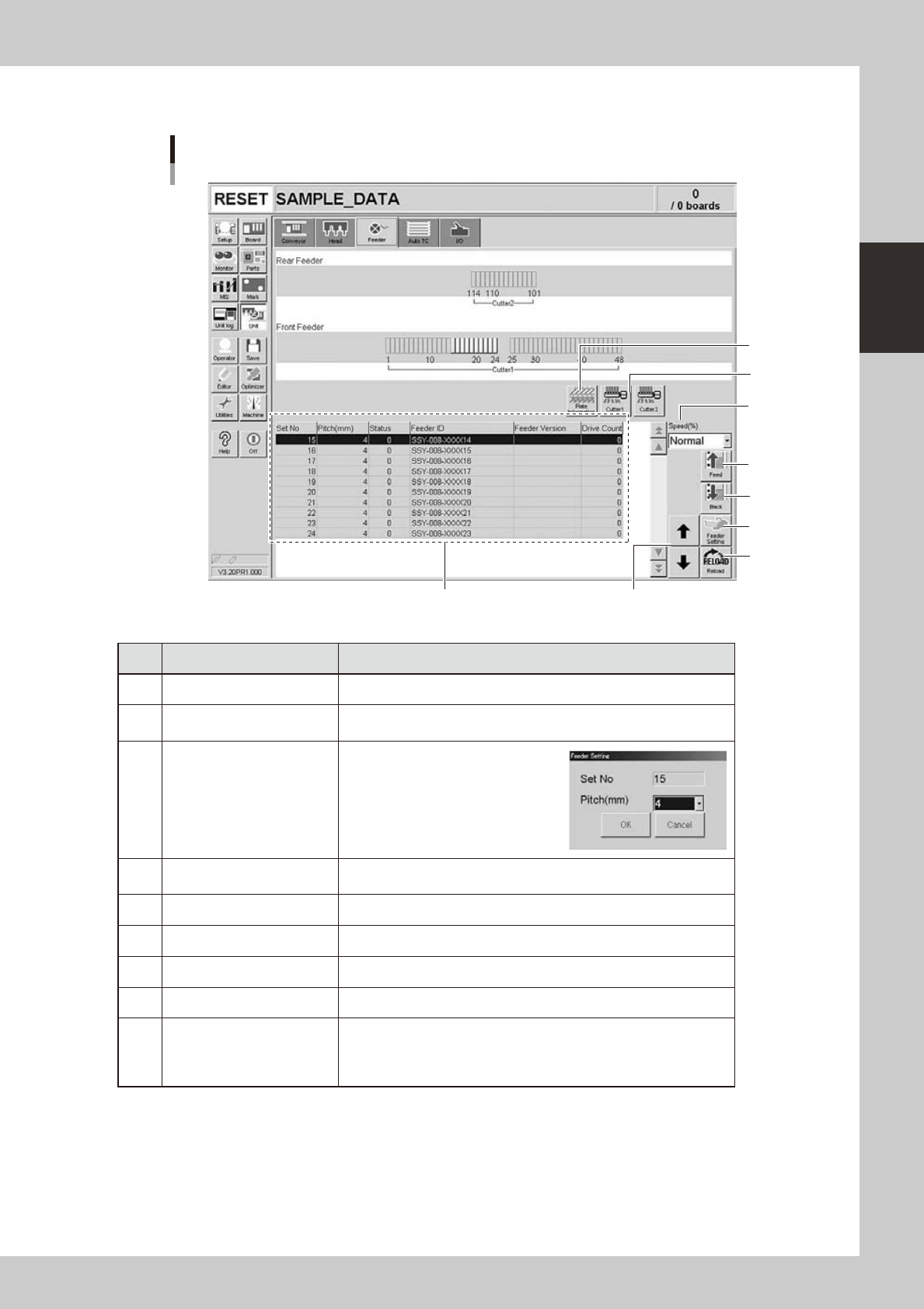
Manual feeder operation
[Unit] – [Feeder] screen
1
4
7
8
2
69
5
3
24210-L4-10
Button name Function
1 Feed Each time pressing this button advances the tape at the specified pitch.
2 Back
Each time pressing this button moves the tape backward at the specified
pitch.
3 Feeder Setting
Pressing this button opens the
feeder setting dialog box that
allows selecting a feed pitch from
2 to 56mm.
Set the feed pitch and press the
[OK] button. The set feeder pitch
is stored in memory.
4 Speed
Select the feed speed from the drop-down list. The selectable speeds
are "Normal", 90, 80, … 10%.
5 Reload Clears the feeder condition (memory) and reloads the setting.
6 Up/down arrows Moves the selected row up or down.
7 Cutter Opens or closes the tape cutter (option).
8 Plate Information Allows you to check the version of the plate board in the feeder plate.
9 Feeder Information
Displays the information of the feeders set on the feeder plate.
The error code number is displayed in the "Status" column.
The details and countermeasure of each error code number are
described in the "SS feeder user's manual".
2-18
2
asic operation
n
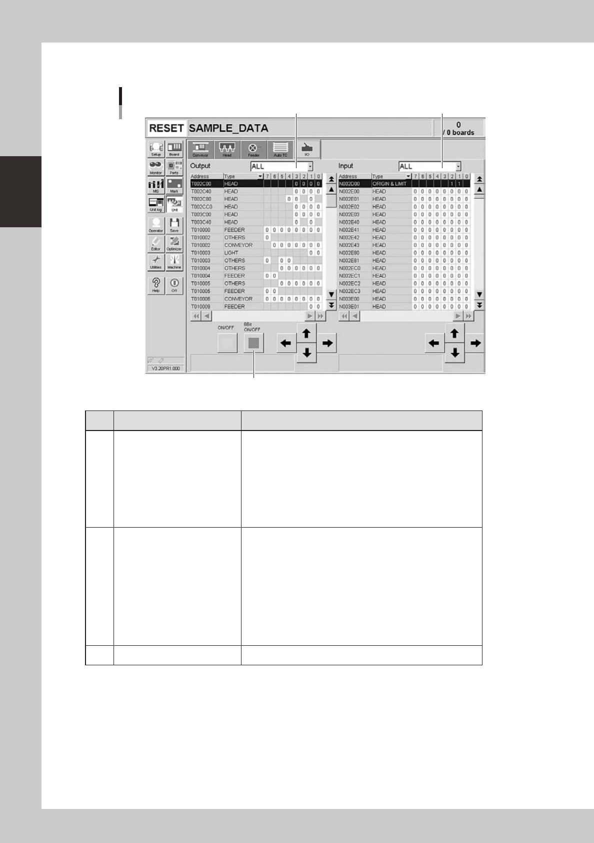
Manual I/O operation
[Unit] – [I/O] screen
1 2
3
24212-L4-00
Button name Function
1 Select output display group
Select the output group for display in the "Output" status list. The
following groups can be selected:
• ALL
• NSTA (nozzle station)
• DUMP STATION
• CONV (conveyor)
• HEAD
• BSTA (blow station)
• OTHERS
2 Select input display group
Select the input group for display in the "Input" status list. The
following groups can be selected:
• INTLCK (interlock)
• SRV (servo origin limit)
• FDR (feeder)
• NSTA (nozzle station)
• CONV (conveyor)
• SPARE
• DUMP STATION
• BSTA (blow station)
• OTHERS
3 ON/OFF Turns the selected valve on or off.