YS24X_Ope_E.pdf - 第94页
2-19 2 asic operation 3. Star ting and stopping the machine This section explains routine procedures for starting and tur ning off the machine according to the flow charts beow . Starting and turning off machine Produc…
2-18
2
asic operation
n
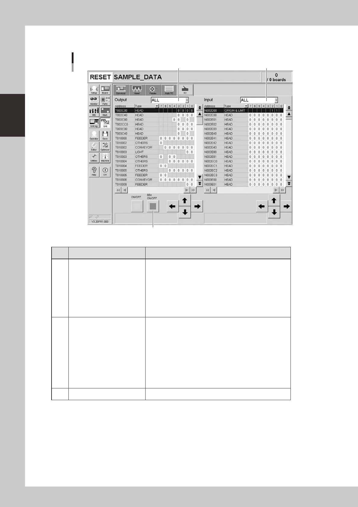
Manual I/O operation
[Unit] – [I/O] screen
1 2
3
24212-L4-00
Button name Function
1 Select output display group
Select the output group for display in the "Output" status list. The
following groups can be selected:
• ALL
• NSTA (nozzle station)
• DUMP STATION
• CONV (conveyor)
• HEAD
• BSTA (blow station)
• OTHERS
2 Select input display group
Select the input group for display in the "Input" status list. The
following groups can be selected:
• INTLCK (interlock)
• SRV (servo origin limit)
• FDR (feeder)
• NSTA (nozzle station)
• CONV (conveyor)
• SPARE
• DUMP STATION
• BSTA (blow station)
• OTHERS
3 ON/OFF Turns the selected valve on or off.
2-19
2
asic operation
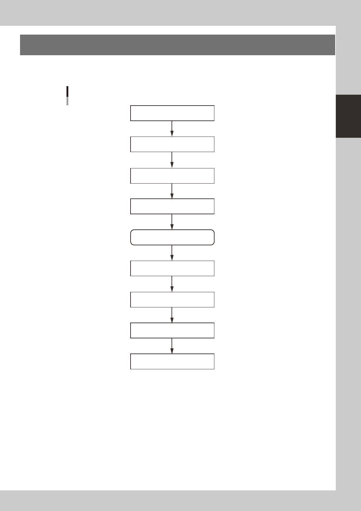
3. Starting and stopping the machine
This section explains routine procedures for starting and turning off the machine according to the flow charts
beow.
Starting and turning off machine
Production (Running)
Press emergency stop button
Return axes to origins
Turn off power switch
Check before operation
Preform return-to-origin
Specify operator
Press [Off] button on screen
Program is loaded.
Return-to-origin dialog box appears.
Move-to-origin dialog box appears.
Shut down dialog box appears.
Finish board production.
Setup screen appears.
Turn on power switch
23201-L4-00
2-20
2
asic operation
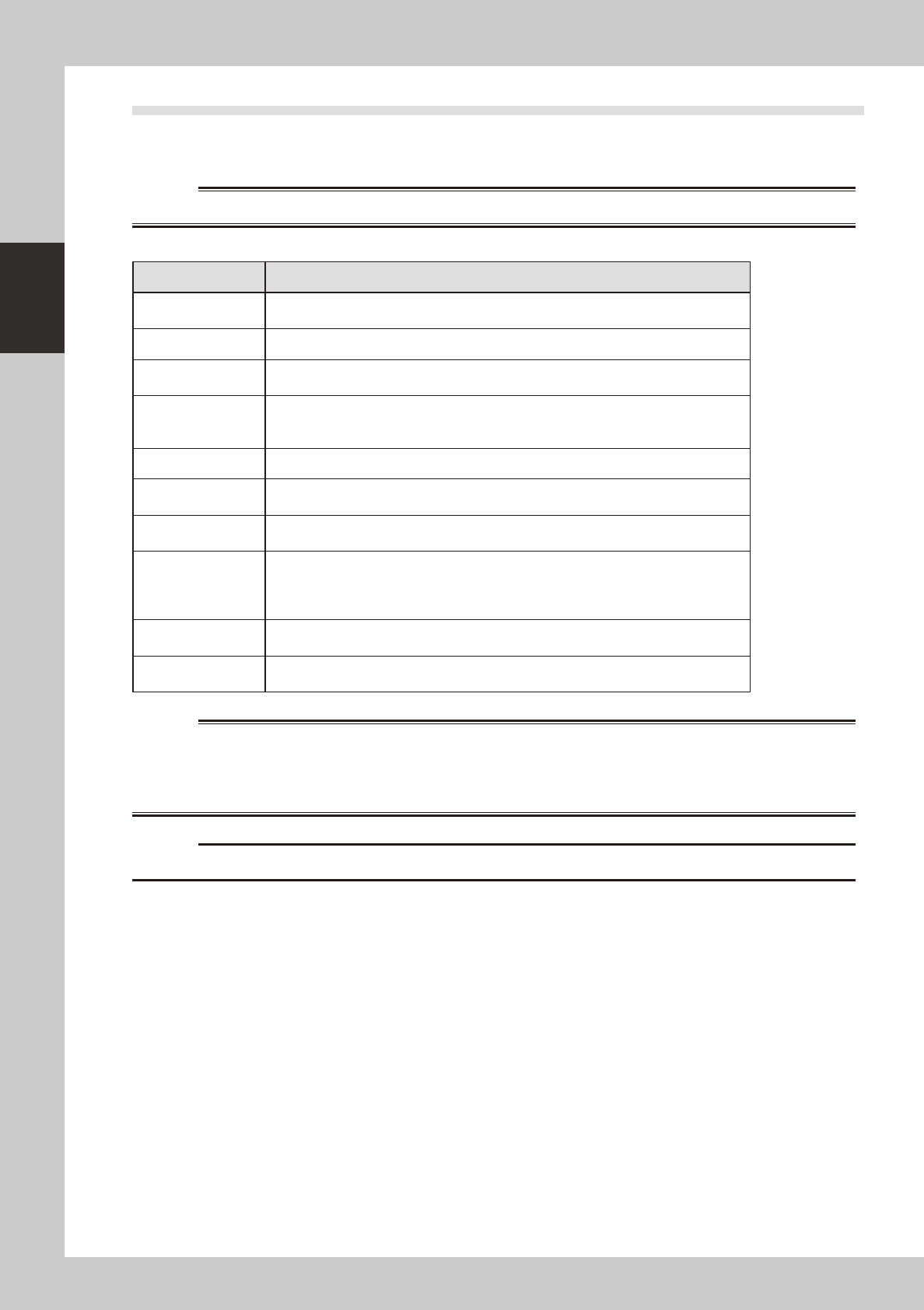
3.1 Pre-operation check
e
Check the following points before turning on the power.
w
WARNING
n
Pre-operation checklist
Check item Checkpoint
Power supply
Check that the specified power is connected to the power supply box located behind the
front lower right panel of the machine.
Safety cover Check that the covers are closed.
Feeder Check that feeders are securely attached to the feeder plate and are not tilted.
Check that no chips or debris adhere to the feeders.
Conveyor Check that no chips or debris are on the conveyor.
Check that the conveyor units do not interfere with each other, such as push-up pins
under the conveyor rails.
Head Check that each nozzle is correctly installed to the head.
Nozzle
Check that the nozzle tips are not nicked, solder does not adhere to the nozzle tips, and
nozzle spring-action is smooth.
Feeder exchange
carriage (option)
Check that no chips or debris are on the feeder plate. Also check that the parts feeders
are securely attached to the feeder plate and no chips and debris adheres to them.
Tray component
supply unit (option)
(sATS
II
)
There is no pallet on the pallet stage.
The magazine door is closed.
No pallets are protruding toward the stage from the magazine.
The sATS
II
is in "RUN" mode.
QFP dump station
(option)
Check that the QFP dump station is securely attached to the feeder plate and also that
no chips and debris adhere to it.
Recovery palette
(Option)
Recovery pallet is set in position.
No parts are placed in the recovery pallet.
w
WARNING
c
The machine will not start operation unless feeder exchange carriages are installed.