00195044-15_UM_VisionTeachStation_DE EN.pdf - 第107页
Vision Teach Station User Manual 3 Ordering information and package supplied 10/2015 Edition 3.2 Cameras and assembly kits 107 3.2.1 Camera type 25 with assembly kit - item no. 03047369-xx (option) 3 3 Fig. 3.2 - 3 Camer…
3 Ordering information and package supplied Vision Teach Station User Manual
3.2 Cameras and assembly kits 10/2015 Edition
106
3.2 Cameras and assembly kits
Designation Item no.
Components,
see section
Camera, type 25, vision teach station
(FC camera) with assembly kit 03047369-xx
3.2.1, page 107
Camera, type 23, vision teach station
(CO camera on C&P20 placement head) with assembly kit 03047371-xx
3.2.2, page 108
Camera, type 33, vision teach station
(IC camera) with assembly kit 03047372-xx
3.2.3, page 109
Camera, type 28, vision teach station
(CO camera on C&P12 placement head) with assembly kit 03047373-xx
3.2.4, page 111
Camera, type 29, vision teach station
(CO camera on C&P6/C&P12 placement head) with assembly kit 03047374-xx
3.2.5, page 112
Camera, type 30, vision teach station
(CO camera on CPP/C&P12 placement head) with assembly kit 03086726-xx
3.2.5, page 112
Camera, type 36, vision teach station
(IC camera) with assembly kit 03054654-xx
3.2.6, page 113
3
3
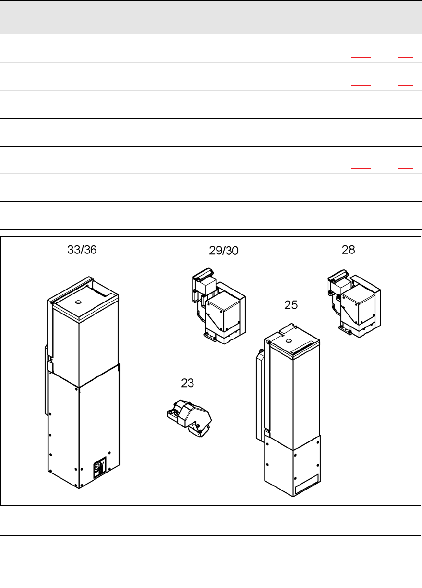
Fig. 3.2 - 2 All the cameras at a glance
NOTE:
The cameras are shown in the mounting position for the vision teach station. This arrangement is
not the same as the installation position in the placement machine. 3
Vision Teach Station User Manual 3 Ordering information and package supplied
10/2015 Edition 3.2 Cameras and assembly kits
107
3.2.1 Camera type 25 with assembly kit - item no. 03047369-xx (option)
3
3
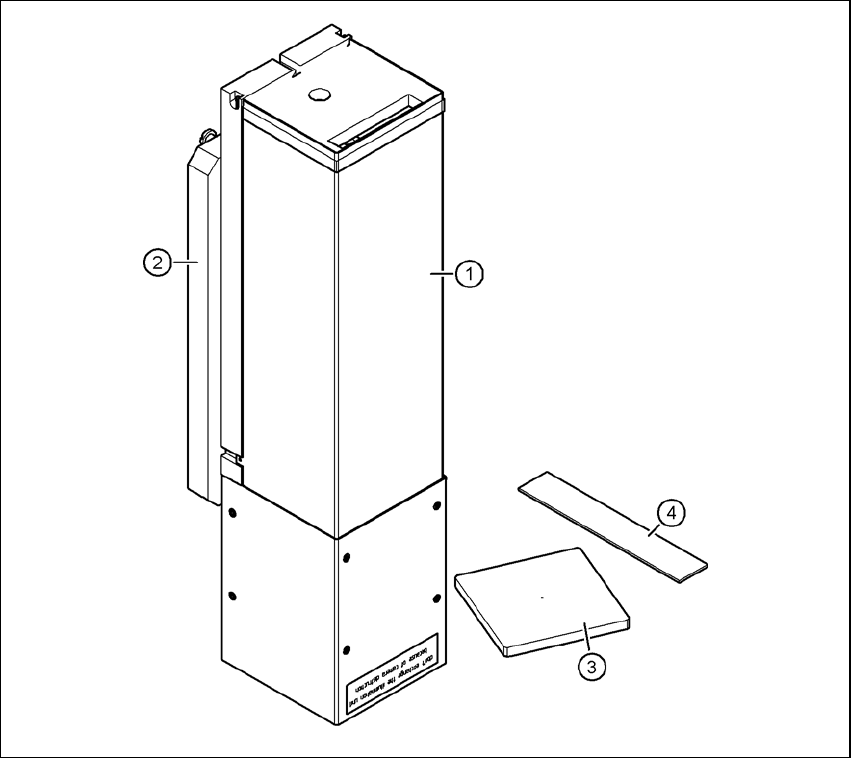
Fig. 3.2 - 3 Camera type 25 - parts
3
(1) Component camera, stationary, P&P, type 25, 16 x 16, digital, item no. 03020578-xx
(2) Mount for camera, type 25, item no. 03039471-xx
(3) Component support, camera type 25/33/36, complete, item no. 03039504-xx
(4) Focus point adjustment guide, camera type 25, item no. 03046389-xx
Cable set for vision teach station, stationary, item no. 03040355-xx
3 Ordering information and package supplied Vision Teach Station User Manual
3.2 Cameras and assembly kits 10/2015 Edition
108
NOTE 3
Figure 3.2 - 3 shows the position at which the component camera (item 1) is mounted on the
vision teach station. The camera is turned 180° about the horizontal on the placement machine.
Only components that are no larger than the field of vision of the component camera (single
measurement) can be taught at the vision teach station. Multiple measurements must be taken
on the machine. Detection of the orientation of asymmetrical package forms is not supported on
the vision teach station.
3.2.2 Camera, type 23 with assembly kit - item no. 03047371-xx (option)
3
3
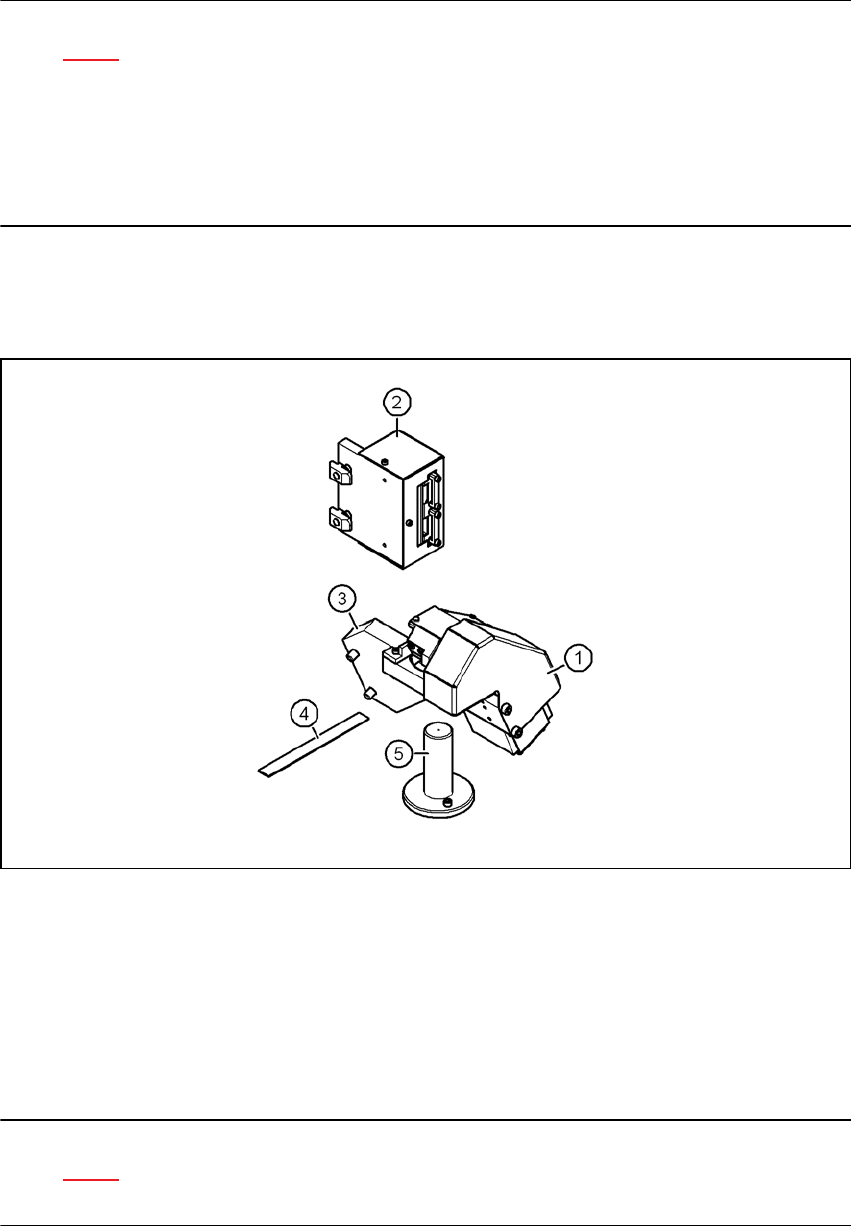
Fig. 3.2 - 4 Camera type 23 - parts
3
(1) Component camera C&P20, type 23, 6 x 6, digital, item no. 03003426-xx
(2) Head camera adapter, vision teach station, item no. 03044405-xx
(3) Mount for camera, type 23, item no. 03039485-xx
(4) Focus point adjustment guide, camera type 23, item no. 03046388-xx
(5) Component support, camera type 23, complete, item no. 03039498-xx
NOTE 3
Figure 3.2 - 4 shows the position at which the component camera (item 1) is mounted on the
vision teach station. The camera is turned 180° about the horizontal on the placement head.