00195044-15_UM_VisionTeachStation_DE EN.pdf - 第138页
6 2nd camera option Vision Teach Station User Manual 6.1 Vision teach station upgrade 10/2015 Edition 138 6.1.4 Connecting two stationary cameras If there is also a stationary camera (SST33, 36 or 25) used on the second …

Vision Teach Station User Manual 6 2nd camera option
10/2015 Edition 6.1 Vision teach station upgrade
137
6 2nd camera option
You can install a second camera on the vision teach station as an option. We can provide the up-
grade package you will need. This package does NOT include the camera and assembly kit, how-
ever, which should be ordered separately.
6.1 Vision teach station upgrade
Order designation
Item no.
Optional 2nd pillar for vision teach station
03063366-xx
6.1.1 Bill of materials
Designation
Item no. Number
Vision teach station pillar
03039431-xx 1
Cable set for vision teach station
03040352-xx 1
Assembly instructions "Optional pillar for vision teach
station" 00196052-xx 1
6.1.2 Component camera
You will find the order data for the component cameras in section 3.2, page 106.
6.1.3 Assembly
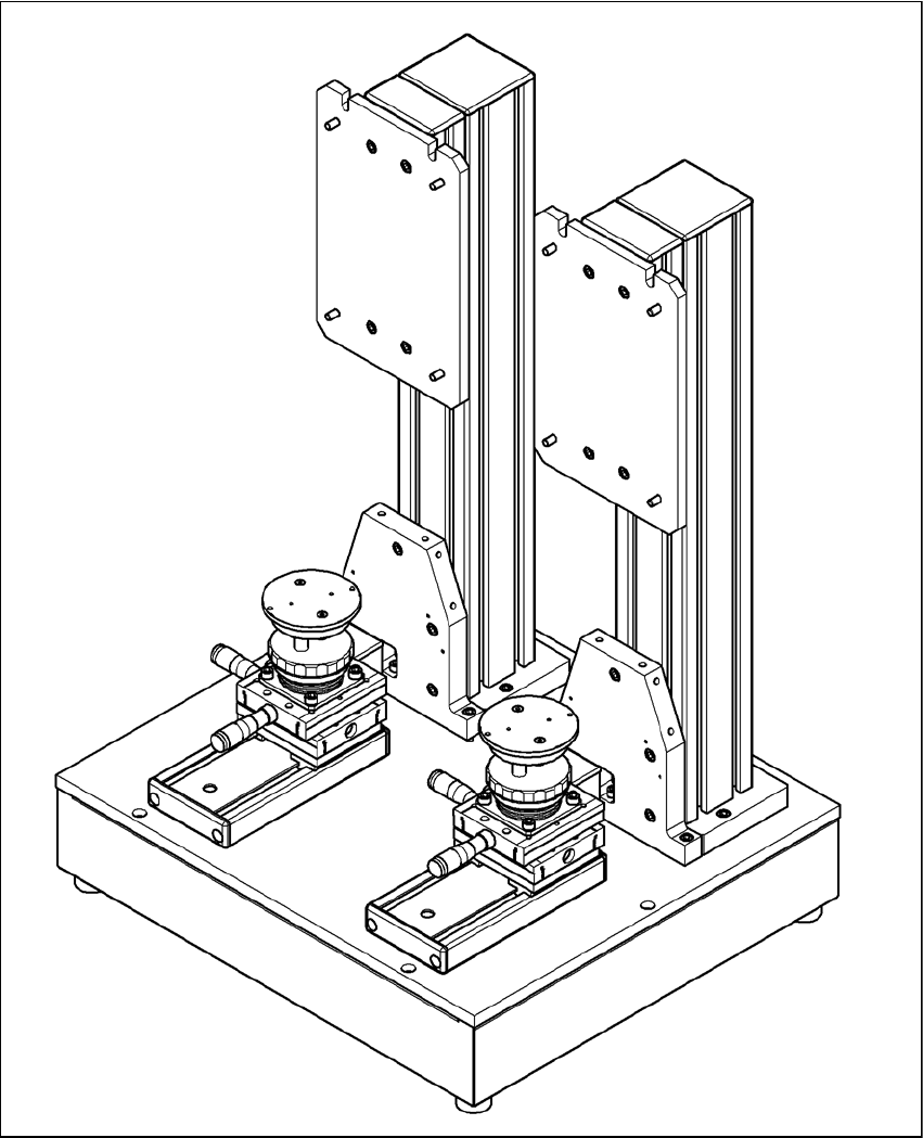
When the vision teach station is converted to two cameras, the pillar and the component positio-
ning table are moved from the middle to the left (see Fig. 6.1 - 1, page 139). The additional pillar
and the component positioning table are fixed to the holes on the right-hand side. The conversion
is described in the enclosed assembly instructions.

6 2nd camera option Vision Teach Station User Manual
6.1 Vision teach station upgrade 10/2015 Edition
138
6.1.4 Connecting two stationary cameras
If there is also a stationary camera (SST33, 36 or 25) used on the second pillar, the main power
supply and the CAN bus are plugged directly into the camera on the first pillar, rather than into the
base module. You will need cable kit 03040352 to do this.
First plug this cable kit into the second, additional camera following the instructions in section
5.1.1, page 119.
Fit the camera onto the second pillar following the instructions in section 5.1.2, page 123.
Then connect the cable 03040352-W1 to connector X5 on the camera on pillar 1. Connector
X5 is difficult to access while the housing cover is fitted.
To access the connector, you should ideally put the vision teach station on the floor and re-
move the dust cover (foam rubber) so that you can see in clearly from above. Connector X5 is
beneath connector X4, or, as shown in Fig. 5.1 - 2, page 120, to the right of X4. The connectors
X4 and X5 are interchangable.
Connect cable 03040352-W2 to connector X12 from cable kit 03040355 (see Fig. 5.1 - 2, page
120, bottom left).
Vision Teach Station User Manual 6 2nd camera option
10/2015 Edition 6.1 Vision teach station upgrade
139
6
Fig. 6.1 - 1 Assembly position for the two pillars