SIPLACE D3 规格说明书英文版 - 第20页
20 Component Feeding Component Changeover Table SIPLACE component changeover tables are stand - alone modules that a re easy to maneuver and can be docked into th e machine. This ensure s that the tab le is accurately po…
19
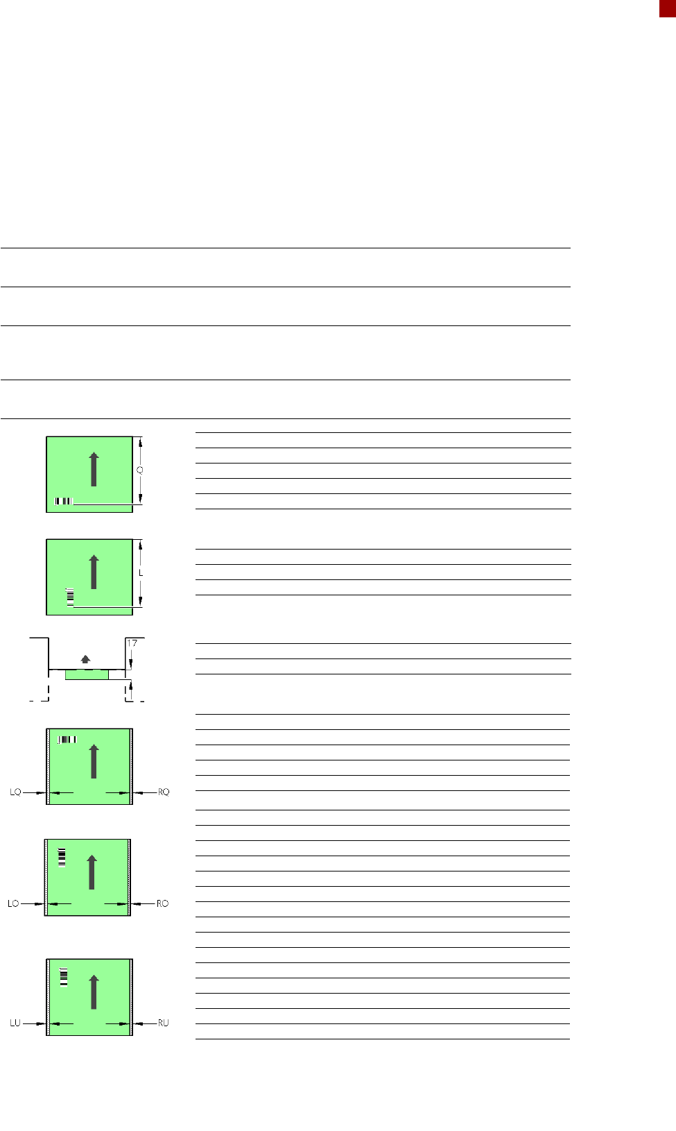
PCB Barcode for Product-Controlled Production
(Option)
Label dimensions Stroke width (W): 0.19 < W 0.3 mm (corresponds to high and medium den-
sity), stroke length: mm, length of the barcode template window: 90 mm
Recommended label
colors
Coding: black, dark green, dark blue, background: white, beige, yellow, orange
(contrast ratio > 70% to DIN 66236)
Code types Code 39, Code 128 / EAN 128, Codabar, 2/5 IATA 2/5 industrial, 2/5 inter-
leaved, UPC, EAN, Pharma Code, EAN Addendum (others available on
request), a barcode filter may be defined
Laser scanner safety Laser diode 670 nm (red) / 1.2 mW
Laser protection class 2, degree of protection IP65
Downstream
machine
Upstream
machine
PCB
PCB barcode scanner 1D on top
PCB barcode scanner 1D on bottom
PCB barcode reader Q [mm]
2D on top 390
1D on top 390
2D on bottom 430
1D on bottom 430
PCB barcode reader L [mm]
1D on top 320 - 350
1D on bottom 380 - 410
PCB barcode reader PCB rear projection [mm]
2D on bottom (dual conveyor) 17
PCB barcode reader LQ [mm] RQ [mm]
2D on top 3 3
1D on top 3 3
2D on bottom 5 5
1D on bottom 5 5
PCB dimensions/conveyor LO [mm] RO [mm]
460 mm SC 3 20
508 mm SC 3 44
216 mm DC1 3 24
250 mm DC1, 450 mm SM1 3 58
216 mm DC2 3 3
250 mm DC2, 450 mm SM2 3 3
PCB dimensions/conveyor LU [mm] RU [mm]
460 mm SC 20 3
508 mm SC 44 3
216 mm DC1 3 3
250 mm DC1, 450 mm SM1 3 3
216 mm DC2 24 3
250 mm DC2, 450 mm SM2 58 3
SC - Single conveyor, DC1/2 - Dual conveyor, track 1/2, SM1/2 - Dual conveyor in Single conveyor mode, track 1/2
If there is a PCB dual conveyor installed on the placement machine, we can provide a special design for
retrofitting the 2D PCB barcode scanner "bottom".
20
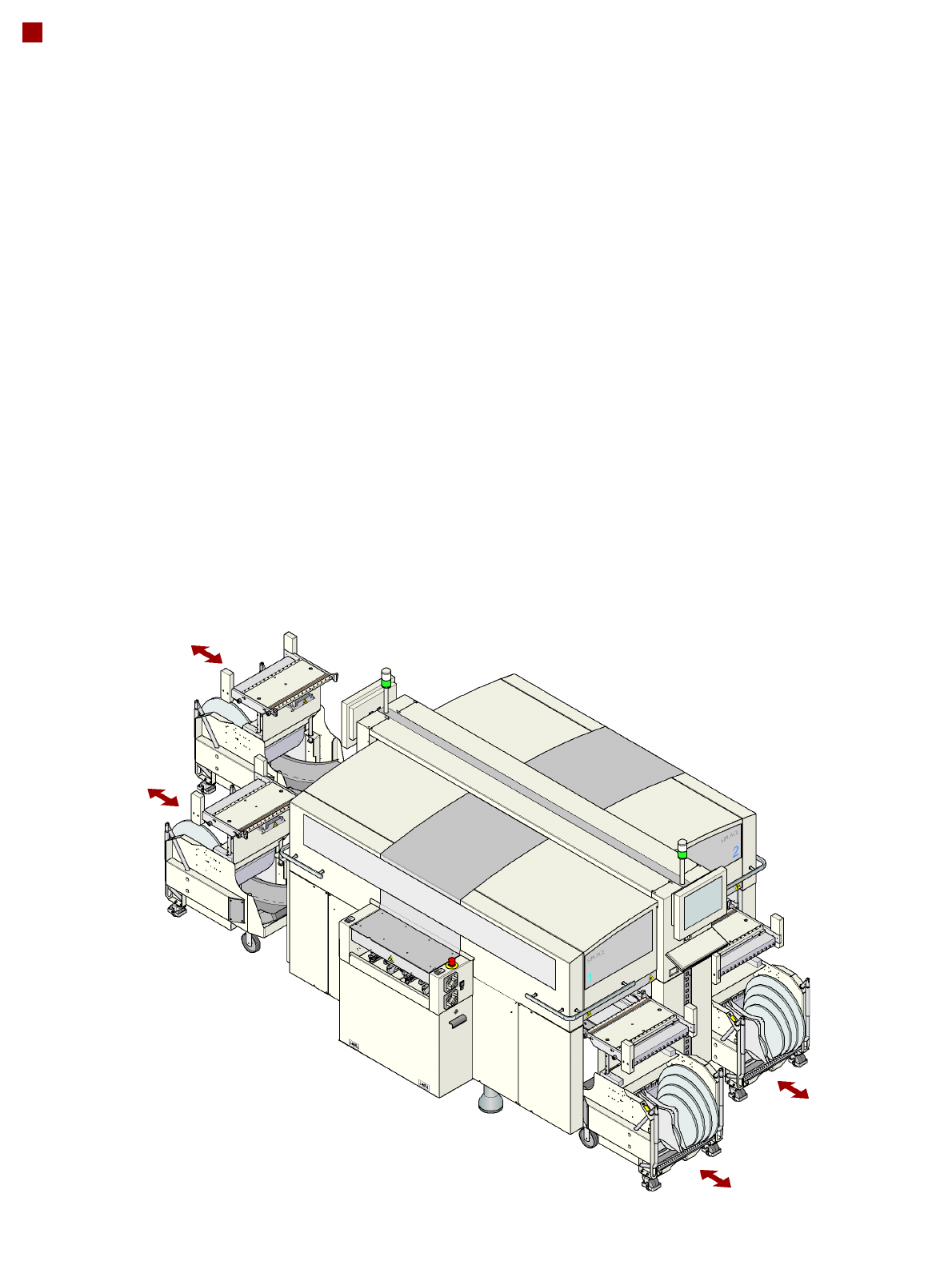
Component Feeding
Component Changeover Table
SIPLACE component
changeover tables are stand-
alone modules that are easy
to maneuver and can be
docked into the machine.
This ensures that the table is
accurately positioned in the
placement machine. Reels
are kept in the tape container
on the component change-
over table. A cutting device
on the machine automatically
cuts the used tape. Option-
ally, a matrix tray changer
may be installed at locations
2 and 4. The component
changeover tables can be
set up directly on the
machine or in an external
set-up area with feeder mod-
ules. The benefits of offline
set-up are that the set-ups
can be prepared without
stopping the line. This allows
the set-up to be changed
very quickly using the
changeover table principle.
The component feeders are
at rest during the placement
process, which means that
components can be refilled
and tapes may be spliced
without stopping the
machine. If an optional com-
ponent barcode reader and
the Setup center option are
installed, it is possible to read
and check the barcodes on
the tape reels. This makes
sure that the component is
allocated to the right track,
and the PCB placement can
be traced using traceability
software.
Dummy feeder modules are
used at unassigned locations
to protect the operators.
21
Component Feeding
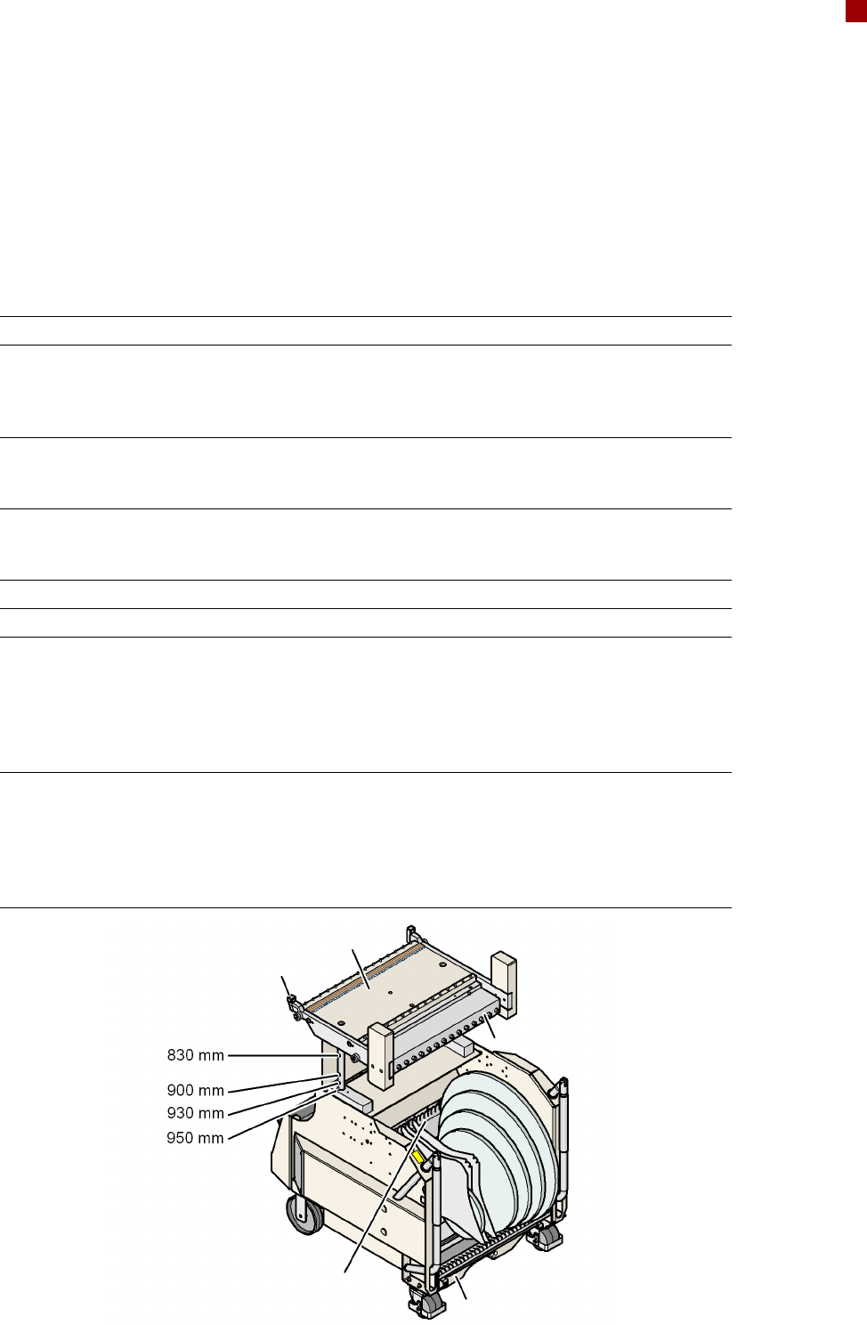
Component Changeover Table
Technical Data
Length x width 752 x 592 mm²
Height 830 mm for 830 mm PCB transport height
900 mm for 900 mm PCB transport height
930 mm for 930 mm PCB transport height
950 mm for 950 mm PCB transport height
Weight
without feeder modules
with feeder module at all locations
88.9 kg
143.7 kg
Reel diameter
standard
maximum
up to 432 mm (17“)
483 mm (19“)
Locations for feeder modules max. 15 (3 x 8 mm S)
Changeover time < 1 minute
Component Feeding 4 component changeover tables with tape
reel holders and integral waste containers
15 slots, 30 mm wide per CO changeover
table
Matrix tray changer rather than a compo-
nent changeover table at locations 2 and 4
Feeder module types Component tapes, bulk cases, stick maga-
zines, Dip module, waffle-pack trays, OEM
feeder modules (surf tape, component dis-
posal module, waffle-pack trays, Jedec
trays, label feeder modules, inline program-
ming feeder modules)
Component feeder table
Centering
Communication unit
Waste container
for remaining empty tape
Tape container