Printer 600 Machine Programming
0$&+,1 (352*5$0 0,1* ,1752'8& 7,21 Software Version 07SP04 User Manual 1.1 CHAPTER 1 MACHINE PROGRAMMING INTRODUCTION This chapter details the pr ocedure for a product setup, in st ages and are as follo ws:…
0$&+,1(352*5$00,1*
,1752'8&7,21
Software Version 07SP04 User Manual 1.1
CHAPTER 1 MACHINE PROGRAMMING
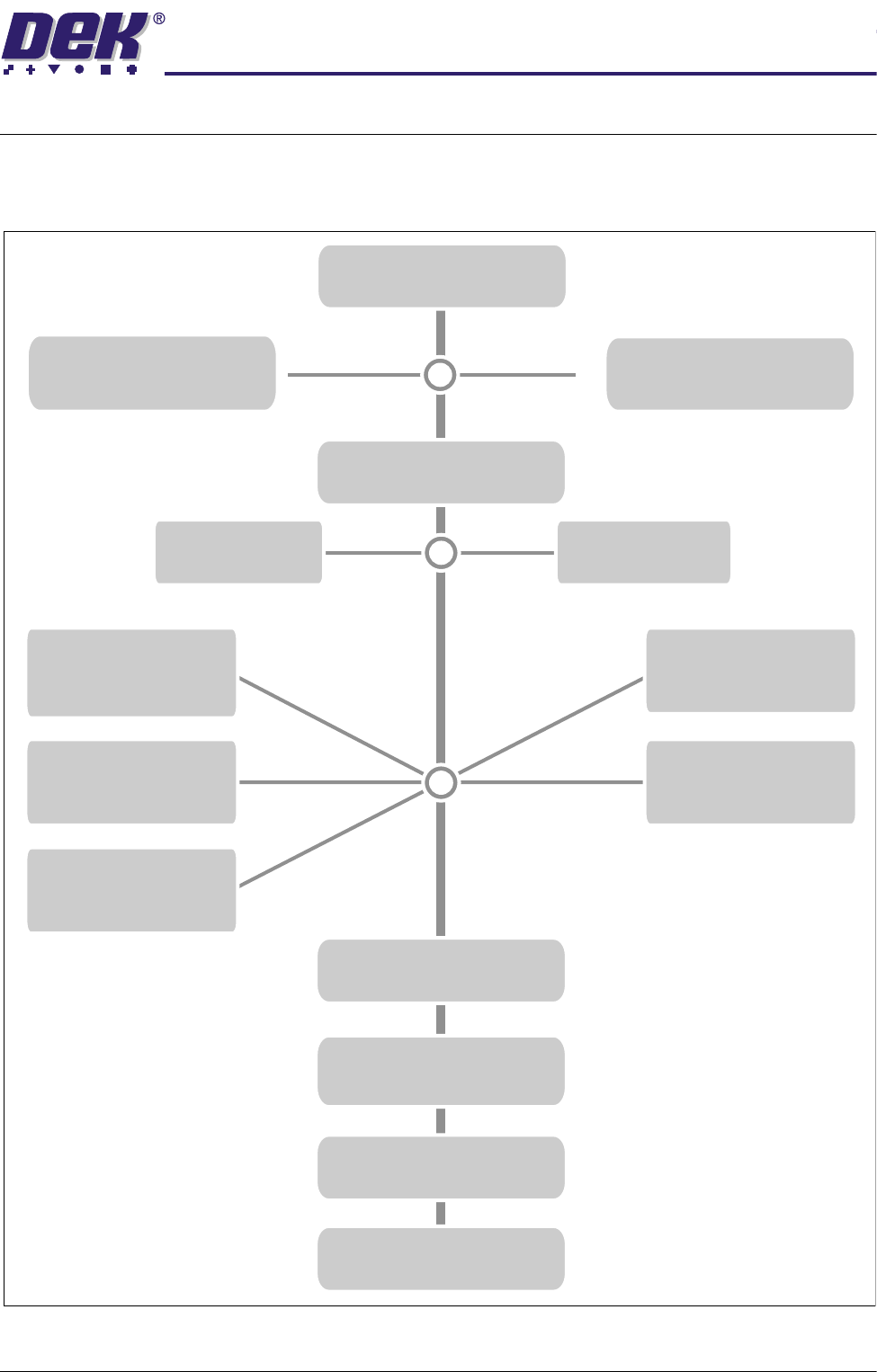
INTRODUCTION This chapter details the procedure for a product setup, in stages and are as
follows:
STAGE 1
POWER UP AND LOG ON
STAGE 2B
LOAD A PRODUCT FILE
STAGE 2A
LOAD A PRODUCT FILE
STAGE 3
EDIT A PRODUCT FILE
STAGE 7
PRINT
Load Paste
IN STEP MODE
STAGE 8
2DI SETUP
STAGE 9
PRINT IN RUN MODE
STAGE 6
VISION SYSTEM SETUP
STAGE 5E
FORMFLEX
& Load Screen
TOOLING
STAGE 5B
VACUUM
& Load Screen
TOOLING
STAGE 5C
DEDICATED
& Load Screen
TOOLING
STAGE 5D
MULTIFLEX
& Load Screen
TOOLING
STAGE 5A
MAGNETIC PILLARS
& Load Screen
TOOLING
STAGE 4A
FIT SQUEEGEES
STAGE 4B
PROFLOW SETUP
Using Function Keys
Using Bar Code
0$&+,1(352*5$00,1*
,1752'8&7,21
1.2 User Manual Software Version 07SP04
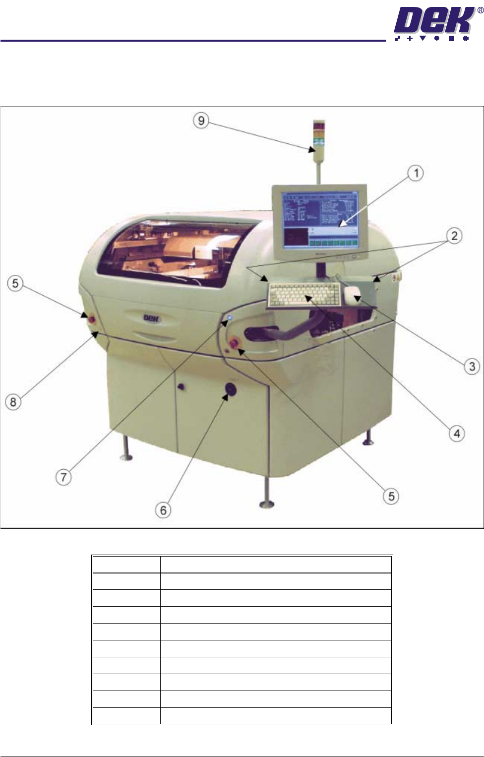
Machine Overview Displayed in graphics below are the different types of machine cover packages
and controls:
Figure 1-1 Front View of Machine with Printhead Covers
Item Description
1 Touchscreen Monitor
2 Two Button Control
3 Mouse
4 Keyboard
5 Emergency Stop Buttons (E Stop)
6 Mains Isolator Switch
7 System Button
8 Paste Roll Lamp Button
9 Tricoloured Beacon
0$&+,1(352*5$00,1*
,1752'8&7,21
Software Version 07SP04 User Manual 1.3
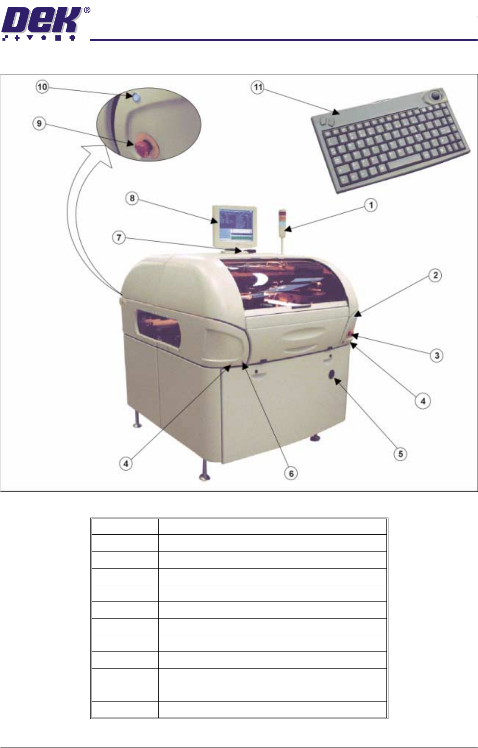
Figure 1-2 Front View of Machine with Printhead Shutter
Item Description
1 Tricoloured Beacon
2 System Button - Front
3 Emergency Stop Button (E Stop) - Front
4 Two Button Control
5 Mains Isolator Switch
6 Paste Roll Lamp Button
7 IR Receiver
8 LCD Monitor
9 Emergency Stop Button (E Stop) - Rear
10 System Button - Rear
11 IR Keyboard/Mouse