Printer 600 Machine Programming.pdf - 第114页
0$&+,1( 352*5$00 ,1* 0(183$5$ 0(7(56 1.114 User Manual Software Ve rsion 07SP04 Y Align W eighting This is only us ed in 3 fi ducial mode and set s a value deter mining where t he Y axis alig nment should be opti m…
0$&+,1(352*5$00,1*
0(183$5$0(7(56
Software Version 07SP04 User Manual 1.113
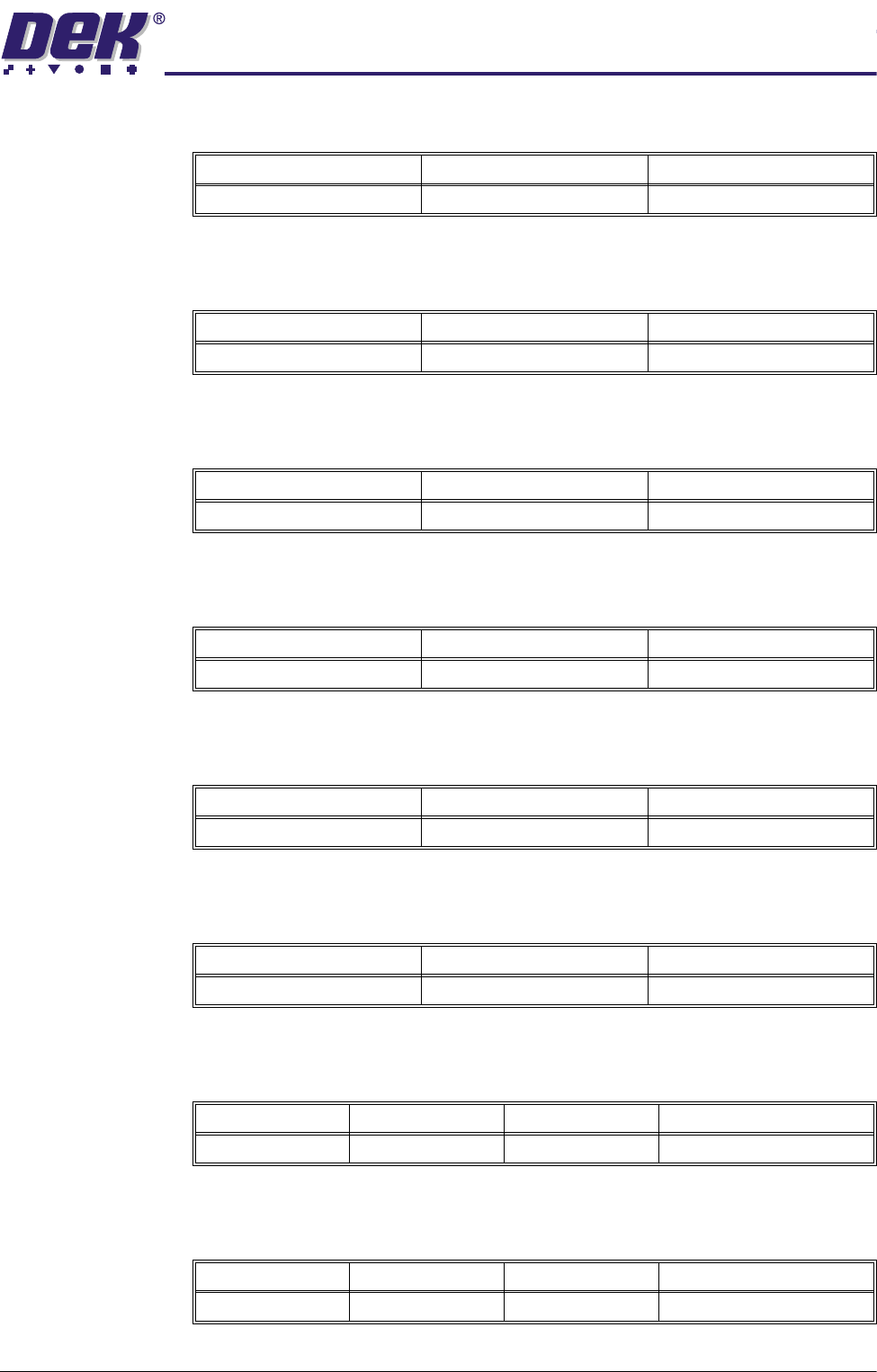
A positive offset moves the print to the right of the board.
Reverse Y Offset Programmable offset of the print on the board when printing from the front.
A positive offset moves the print to the rear of the board.
Reverse Theta
Offset
Programmable offset of the print on the board when printing from the front.
A positive offset moves the print in a clockwise direction.
Screen X Forward Nominal position of the X front screen actuator which ensures that correspond-
ing stencil and board fiducials can be viewed from a single camera position.
Screen X Rear Nominal position of the X rear screen actuator which ensures that correspond-
ing stencil and board fiducials can be viewed from a single camera position.
Screen Y Axis Nominal position of the Y screen actuator which ensures that corresponding
stencil and board fiducials can be viewed from a single camera position.
Alignment
Weighting
This is only used in 2 fiducial mode and sets a value determining how much of
the fiducial spacing error is assigned to fiducial 2.
X Align Weighting This is only used in 3 fiducial mode and sets a value determining where the X
axis alignment should be optimized.
Minimum Maximum Increment
-1.0mm +1.0mm 0.004mm
Minimum Maximum Increment
-1.0mm +1.0mm 0.004mm
Minimum Maximum Increment
-1000 arc seconds +1000 arc seconds 2 arc seconds
Minimum Maximum Increment
-20.0mm +20.0mm 0.004mm
Minimum Maximum Increment
-20.0mm +20.0mm 0.004mm
Minimum Maximum Increment
-10.0mm +10.0mm 0.004mm
Minimum Maximum Increment Default
0% 100% 1% 50% (see vision system)
Minimum Maximum Increment Default
0% 100% 1% 50% (see vision system)
0$&+,1(352*5$00,1*
0(183$5$0(7(56
1.114 User Manual Software Version 07SP04
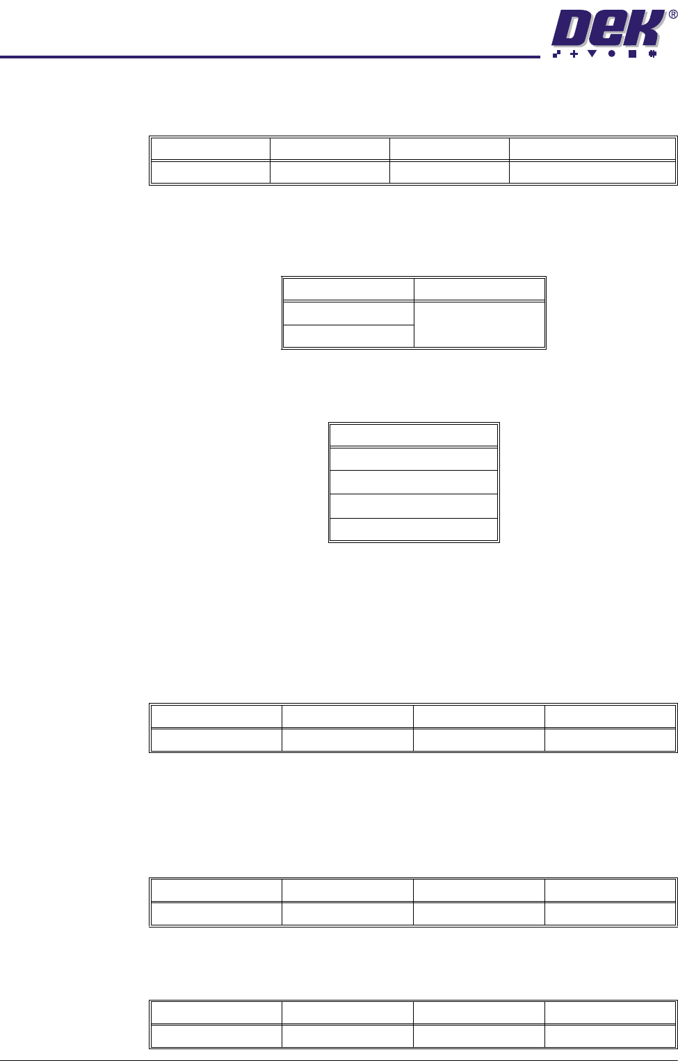
Y Align Weighting This is only used in 3 fiducial mode and sets a value determining where the Y
axis alignment should be optimized.
Alignment Mode This parameter determines the mode used for board to stencil alignment. The
Non Vision option is only available from the configuration file. Options available
are:
Tooling Type This determines which type of board support is to be used with this particular
product. Options are:
NOTE
Vac for Flex is only available while Feature License Authentication asserts that
Flexible Board Printing is permitted.
Vacuum Sensor
Delay
This parameter determines the length of time after the vacuum tooling has been
switched on before the vacuum sensor is checked, to allow a vacuum seal to
be achieved.
NOTE
This parameter is only available if Tooling Type is set to Vacuum.
Flatten Vacuum
Delay
This parameter determines the duration of vacuum applied whilst the board is
pressed against the underside of the stencil with Vac for Flex enabled.
Separation
Vacuum Delay
This parameter determines the duration of vacuum applied after printing and
before the rising table is lowered to separation height with Vac for Flex enabled.
Minimum Maximum Increment Default
0% 100% 1% 50% (see vision system)
Options Available Default
2 Fiducial 2 Fiducial
3 Fiducial
Options
Vacuum
Magnetic Pillars
AutoFlex
Vac for Flex
Minimum Maximum Increment Default
0.1 sec 3.0 secs 0.1 sec 1.5 secs
Minimum Maximum Increment Default
0 sec 5 secs 0.1 sec 2 secs
Minimum Maximum Increment Default
0 sec 5 secs 0.1 sec 2 secs

0$&+,1(352*5$00,1*
0(183$5$0(7(56
Software Version 07SP04 User Manual 1.115
Tooling Deviation This parameter sets the extent of tooling deviation before a warning message
is posted.
Board Stop X This parameter determines the distance from the centre line of the machine to
the board stop position.
NOTE
Not used while the remote board stop is fitted.
Board Stop Y This parameter determines the distance from the fixed rail to the board stop
position.
NOTE
Not used while the remote board stop is fitted.
Right Feed Delay This parameter sets a time delay on the board stop to allow for irregular shaped
boards when fed from the right.
NOTE
Not used while remote board stop is fitted.
Board-At-Stop
Run-On
This parameter sets the period of time for which the belts continue to run after
the board has reached the board stop.
NOTE
Only used on printhead cover machines while high throughput conveyor ena-
bled.
Remote Board
Stop X
This parameter determines the displacement of the remote board stop from the
camera reference position.
NOTE
Only used while remote board stop is fitted.
Minimum Maximum Increment Default
0% 50% 0.25% 20%
Minimum Maximum Increment Default
0.0mm 255.0mm 0.1mm Half of the board length set in the board
file, (board located centrally)
Minimum Maximum Increment Default
20.0mm Board width - 15.0mm 0.1mm Two thirds of the board width
Minimum Maximum Increment
0 sec 3 secs 0.1 sec steps
Minimum Maximum Increment Default
0.0 Secs 1.0 Secs 0.1 Secs 0.3 Secs
Minimum Maximum Increment Default
Minimum board length ÷ 2 Board length 0.1mm Board length ÷ 2