Printer 600 Machine Programming.pdf - 第115页
0$&+,1 (352*5$0 0,1* 0(18 3$5 $0( 7(5 6 Software Version 07SP04 User Manual 1.115 T ooling Devi ation This p arameter sets the ex tent o f tooli ng devia tion befor e a warn ing message is posted. Board S top X Thi…
0$&+,1(352*5$00,1*
0(183$5$0(7(56
1.114 User Manual Software Version 07SP04
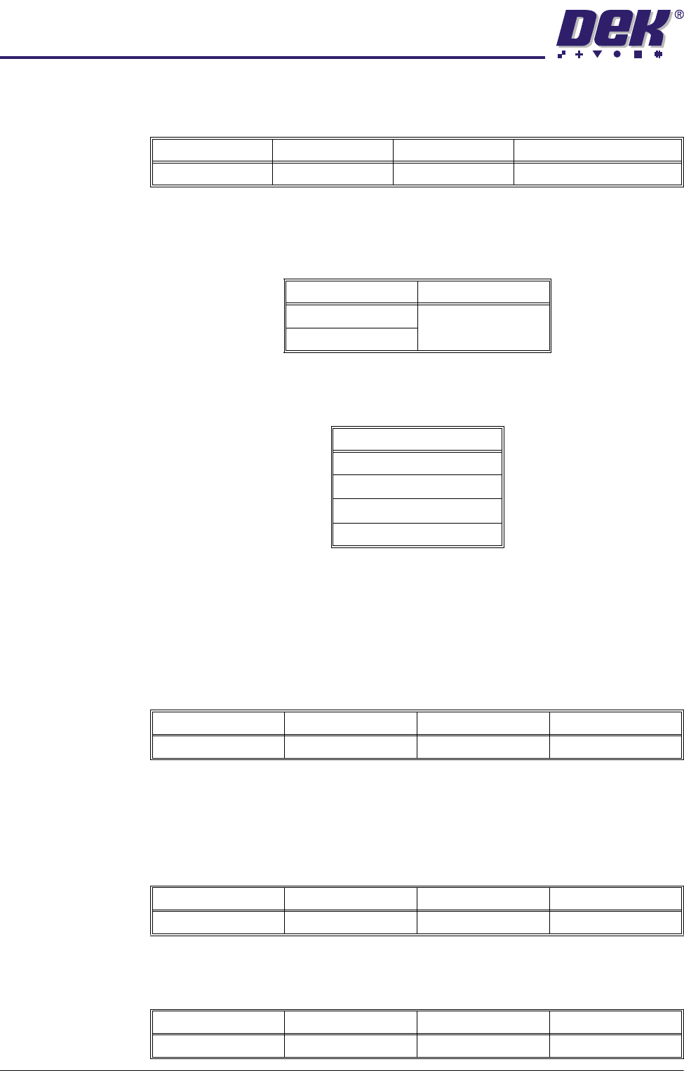
Y Align Weighting This is only used in 3 fiducial mode and sets a value determining where the Y
axis alignment should be optimized.
Alignment Mode This parameter determines the mode used for board to stencil alignment. The
Non Vision option is only available from the configuration file. Options available
are:
Tooling Type This determines which type of board support is to be used with this particular
product. Options are:
NOTE
Vac for Flex is only available while Feature License Authentication asserts that
Flexible Board Printing is permitted.
Vacuum Sensor
Delay
This parameter determines the length of time after the vacuum tooling has been
switched on before the vacuum sensor is checked, to allow a vacuum seal to
be achieved.
NOTE
This parameter is only available if Tooling Type is set to Vacuum.
Flatten Vacuum
Delay
This parameter determines the duration of vacuum applied whilst the board is
pressed against the underside of the stencil with Vac for Flex enabled.
Separation
Vacuum Delay
This parameter determines the duration of vacuum applied after printing and
before the rising table is lowered to separation height with Vac for Flex enabled.
Minimum Maximum Increment Default
0% 100% 1% 50% (see vision system)
Options Available Default
2 Fiducial 2 Fiducial
3 Fiducial
Options
Vacuum
Magnetic Pillars
AutoFlex
Vac for Flex
Minimum Maximum Increment Default
0.1 sec 3.0 secs 0.1 sec 1.5 secs
Minimum Maximum Increment Default
0 sec 5 secs 0.1 sec 2 secs
Minimum Maximum Increment Default
0 sec 5 secs 0.1 sec 2 secs
0$&+,1(352*5$00,1*
0(183$5$0(7(56
Software Version 07SP04 User Manual 1.115
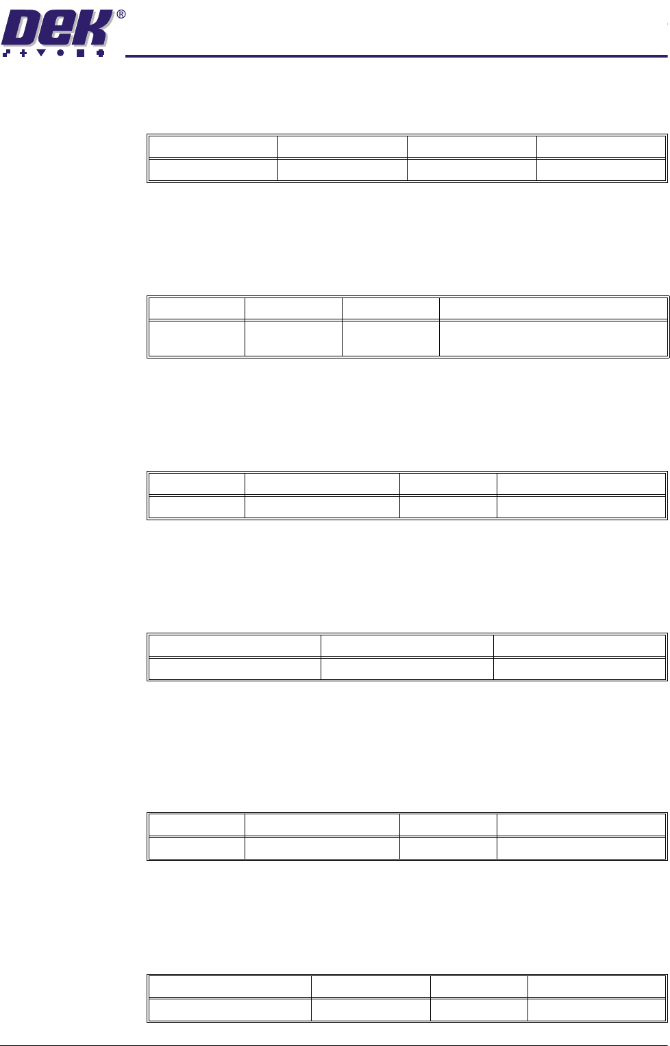
Tooling Deviation This parameter sets the extent of tooling deviation before a warning message
is posted.
Board Stop X This parameter determines the distance from the centre line of the machine to
the board stop position.
NOTE
Not used while the remote board stop is fitted.
Board Stop Y This parameter determines the distance from the fixed rail to the board stop
position.
NOTE
Not used while the remote board stop is fitted.
Right Feed Delay This parameter sets a time delay on the board stop to allow for irregular shaped
boards when fed from the right.
NOTE
Not used while remote board stop is fitted.
Board-At-Stop
Run-On
This parameter sets the period of time for which the belts continue to run after
the board has reached the board stop.
NOTE
Only used on printhead cover machines while high throughput conveyor ena-
bled.
Remote Board
Stop X
This parameter determines the displacement of the remote board stop from the
camera reference position.
NOTE
Only used while remote board stop is fitted.
Minimum Maximum Increment Default
0% 50% 0.25% 20%
Minimum Maximum Increment Default
0.0mm 255.0mm 0.1mm Half of the board length set in the board
file, (board located centrally)
Minimum Maximum Increment Default
20.0mm Board width - 15.0mm 0.1mm Two thirds of the board width
Minimum Maximum Increment
0 sec 3 secs 0.1 sec steps
Minimum Maximum Increment Default
0.0 Secs 1.0 Secs 0.1 Secs 0.3 Secs
Minimum Maximum Increment Default
Minimum board length ÷ 2 Board length 0.1mm Board length ÷ 2
0$&+,1(352*5$00,1*
0(183$5$0(7(56
1.116 User Manual Software Version 07SP04
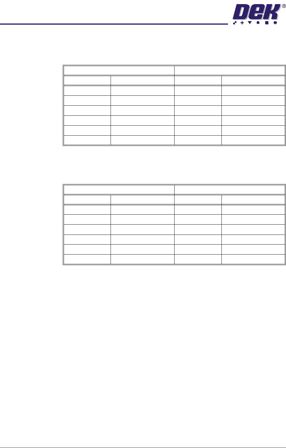
Paste Start This parameter determines the start position of the paste dispense measured
from the centre line of the machine. The limits depend on the type of stencil
fitted.
Paste Stop This parameter determines the stop position of the paste dispense measured
from the centre line of the machine. The maximum value depends on the type
of stencil fitted.
SPC Configuration This preference allows the user to set up the Machines SPC operation. On
selecting the SPC Configuration by pressing the Incr. or Decr. buttons, a window
opens and the menu bar changes.
NOTE
See the SPC Configuration section in this chapter for further details.
2Di Parameters For a list of all the 2Di parameters, refer to the 2D Inspection Chapter later in
this manual.
Minimum Maximum
Adapter Start Position Adapter Start Position
No Adapter -255.0mm No Adapter +255.0mm
255 -230.0mm 255 +230.0mm
Sanyo -210.0mm Sanyo +210.0mm
Heraeus -172.0mm Heraeus +172.0mm
249 -215.0mm 249 +215.0mm
Default - half the board length Default + half the board length
Minimum Maximum
Adapter Start Position Adapter Start Position
No Adapter -255.0mm No Adapter +255.0mm
255 -230.0mm 255 +230.0mm
Sanyo -210.0mm Sanyo +210.0mm
Heraeus -172.0mm Heraeus +172.0mm
249 -215.0mm 249 +215.0mm
Default - half the board length Default + half the board length