Printer 600 Machine Programming.pdf - 第117页
0$&+,1 (352*5$0 0,1* 63&&21 ),*85$7,21 Software Version 07SP04 User Manual 1.117 SPC CONFIGURA TION When the cursor on t he Edit Current Process Parameter s p age highligh ts the SPC Configuration opt ion a…
0$&+,1(352*5$00,1*
0(183$5$0(7(56
1.116 User Manual Software Version 07SP04
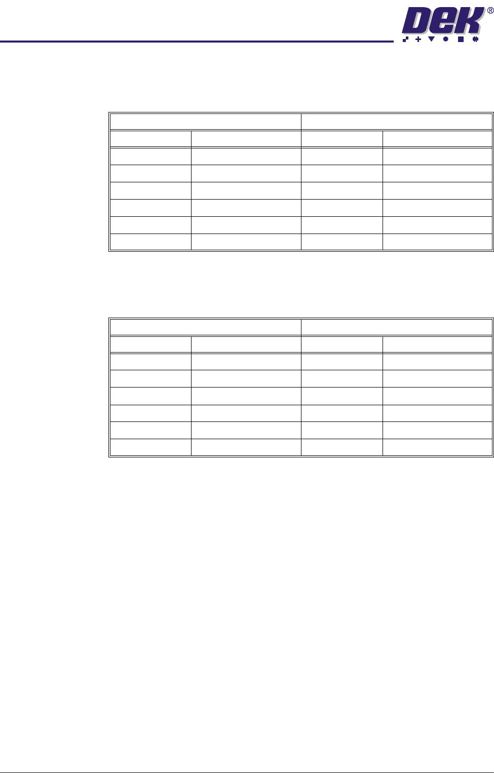
Paste Start This parameter determines the start position of the paste dispense measured
from the centre line of the machine. The limits depend on the type of stencil
fitted.
Paste Stop This parameter determines the stop position of the paste dispense measured
from the centre line of the machine. The maximum value depends on the type
of stencil fitted.
SPC Configuration This preference allows the user to set up the Machines SPC operation. On
selecting the SPC Configuration by pressing the Incr. or Decr. buttons, a window
opens and the menu bar changes.
NOTE
See the SPC Configuration section in this chapter for further details.
2Di Parameters For a list of all the 2Di parameters, refer to the 2D Inspection Chapter later in
this manual.
Minimum Maximum
Adapter Start Position Adapter Start Position
No Adapter -255.0mm No Adapter +255.0mm
255 -230.0mm 255 +230.0mm
Sanyo -210.0mm Sanyo +210.0mm
Heraeus -172.0mm Heraeus +172.0mm
249 -215.0mm 249 +215.0mm
Default - half the board length Default + half the board length
Minimum Maximum
Adapter Start Position Adapter Start Position
No Adapter -255.0mm No Adapter +255.0mm
255 -230.0mm 255 +230.0mm
Sanyo -210.0mm Sanyo +210.0mm
Heraeus -172.0mm Heraeus +172.0mm
249 -215.0mm 249 +215.0mm
Default - half the board length Default + half the board length

0$&+,1(352*5$00,1*
63&&21),*85$7,21
Software Version 07SP04 User Manual 1.117
SPC CONFIGURATION
When the cursor on the Edit Current Process Parameters page highlights the
SPC Configuration option and Incr. or Decr. are pressed an SPC Configuration
Window opens and two extra menu options become available:
Configuration
Window
The configuration window allows the user to setup the machines SPC operation.
Data Output Rate Two rates of data output are available as follows:
Every Cycle - Outputs SPC data every cycle except for the camera data, which
is output dependant upon the settings of the parameters start rate, sample rate
and start rate limit.
On Inspect - Outputs all SPC data at a rate dependant upon the settings of the
parameters start rate, sample rate and start rate limit.
Start Rate Limit Sets the amount of SPC output cycles at the start rate. When this limit is
reached the sample rate parameter becomes the active SPC output rate. The
range is 0-100, where 0 = continuous SPC output at the start rate.
NOTE
Setting both start rate limit and sample rate to zero causes continuous SPC
output at the start rate.
Start Rate Sets the initial SPC output rate, for setting up a line. If start rate is set to 10,
SPC data is output every 10 cycles until the start rate limit is reached, when the
rate becomes that set in the sample rate parameter. The range is 1-100.
Sample Rate Sets the rate of SPC output after the start rate limit has been reached. The
range is 0-100, where 0 = continuous SPC outputs at start rate. If sample rate
is set to 15, SPC data is output every 15 cycles after the start rate limit is
reached.
Edit
Outputs
Edit
Limits
Next Previous Incr. Decr. Exit
SPC Configuration Page
DATA OUTPUT RATE
START RATE
SAMPLE RATE
START RATE LIMIT
SPC DATA MODE
SPC FORMAT
UPDATE ON START-UP
ALIGN INSPECT MODE
EVERY CYCLE
1
10
10
NONE
WINDOWS
NO
PRE PRINT
cycles
cycles
cycles

0$&+,1(352*5$00,1*
63&&21),*85$7,21
1.118 User Manual Software Version 07SP04
The table below illustrates how the use of the following SPC Configuration
parameters can vary the sampling of SPC Output Parameters from the
machine:
• Data Output Rate
• Start Rate
• Sample Rate
• Start Rate Limit
NOTE
Machine Data and Camera Data are defined in the table in SPC Output
Parameters section.
SPC Data Mode Six modes of data transfer are available as follows:
• None - No SPC data is output at any time.
• Remote - The data is written to a file called READINGS.DEK located on a
remote network drive.
• Serial - The data is output from the machines serial SPC port.
• Disk - The data is written to a file called READINGS.DEK located on the
machines local drive.
• Serial + Remote - Outputs data in both modes.
• Serial + Disc - Outputs data in both modes.
SPC Format All data, irrespective of SPC data mode, is in the selected SPC format, options
are: DOS or Windows.
1 2 3 4 5 6 7 8 9 1011121314151617181920 2122232425262728293031323334353637383940
Machine Cycles
Start Rate
Sample Rate
Start Rate Limit
Every Cycle
Every Cycle
Every Cycle
Every Cycle
Every Cycle
On Inspect
On Inspect
On Inspect
On Inspect
On Inspect
100
1
00
1510
1510
2510
2510
5120
5
120
1510
15
10
X
X
XXXXXXXXX XXXXXXXXXXXXXXXXXXXXXXXXXX
XX
X
00000000000 00000000000000000000000000000
XXXXXXXXXXXXXXXXXXXXXXXXXXXXXX XXXXXXXXXX
000000000000000000000000000000 0000000000
XXXXXXXXXXXXXXXXXXXXXXXXXXXXXX XXXXXXXXXX
00000 0 0 0 0 0 0
XXXXX X X X X X X
00000 0 0 0 0 0 0
XXXXXX
X
XXXXXXXXXXXXXXXXXXXXXXXXXXXXXXXXX
0 0 0 000000 00000 0000 000000
X X X XXXXXX XXXXX XXXX XXXXXX
0 0 0 000000 00000 0000 000000
XXXXX X X X
00000 0 0 0
XXXXXXXXXXXXXXXXXXXXXXXXXXXXXX XXXXXXXXXX
00000 0 0 0
XXXXXXXXXX X X X X X X
0000000000 0 0 0 0 0 0
X
XXXXXXXX
X
X XXXXXXXXXXXXX XXXXXXXXXXXXXX
X
0000000000
0
000 0
X
0
Machine DataX
0
Legend
Camera Data