Printer 600 Machine Programming.pdf - 第44页
0$&+,1( 352*5$00 ,1* 67$*(' 08/7,)/( ;722/,1* 1.44 User Manual Software Ve rsion 07SP04 NOTE Ensure that in Set Prefs, Generic T ooling and Auto Rail Wid th ar e set to Enab le d. 6. If th ere is a screen…
0$&+,1(352*5$00,1*
67$*('08/7,)/(;722/,1*
Software Version 07SP04 User Manual 1.43
STAGE 5D - MULTIFLEX TOOLING
WARNING
BOARD CLAMPS. EXTREME CARE MUST BE EXERCISED WHEN WORKING IN
THE TOOLING AREA OF THE MACHINE TO AVOID INJURY. THE FOILS ON THE
FRONT AND REAR BOARD CLAMPS ARE VERY SHARP.
CAUTION
BOARD CLAMPS.
Care must be taken to ensure that the board clamps are
not damaged when removing or replacing tooling.
NOTE
Setting up the MultiFlex tooling is to be performed off the machine.
1. Create a box the same size as the board using the side plates.
2. Use the board width and board length dimensions to position the box
correctly.
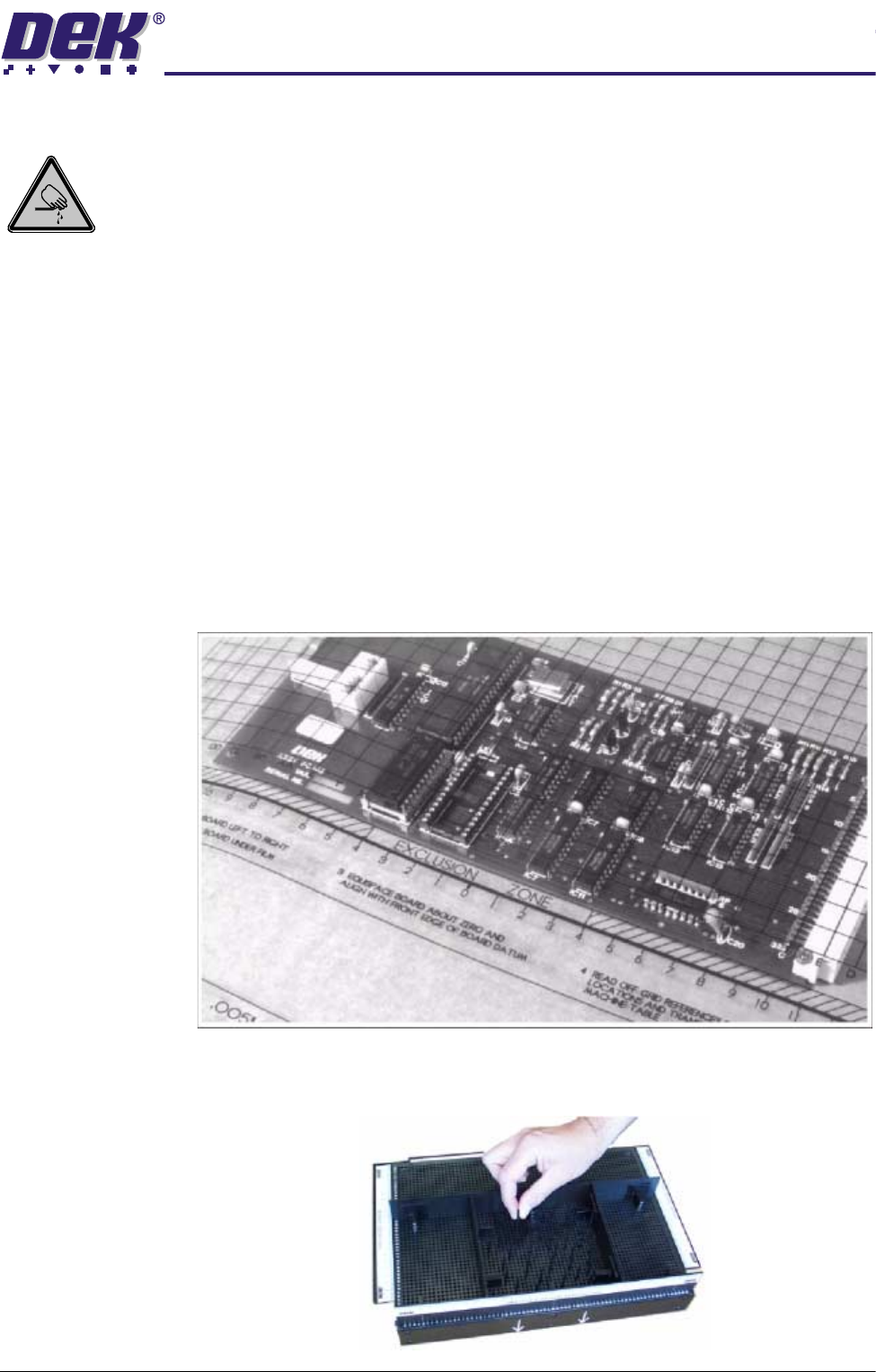
3. Place the PCB on a flat surface, component side up.
4. Position the acetate template, supplied with the tooling, over the PCB such
that the front edge of the board is aligned with the arrow indicators on the
template. Ensure that the centreline of the board is aligned with the template
zero.
5. Using the grid coordinates marked on the template, position pins which
coincide with gaps between the underside board components.
0$&+,1(352*5$00,1*
67$*('08/7,)/(;722/,1*
1.44 User Manual Software Version 07SP04
NOTE
Ensure that in Set Prefs, Generic Tooling and Auto Rail Width are set to
Enabled.
6. If there is a screen loaded continue with Step 7. If there is no screen loaded
go to Step 12.
7. Select Change Screen (F5). The message ‘Open Front Cover and
Remove Screen’ is displayed.
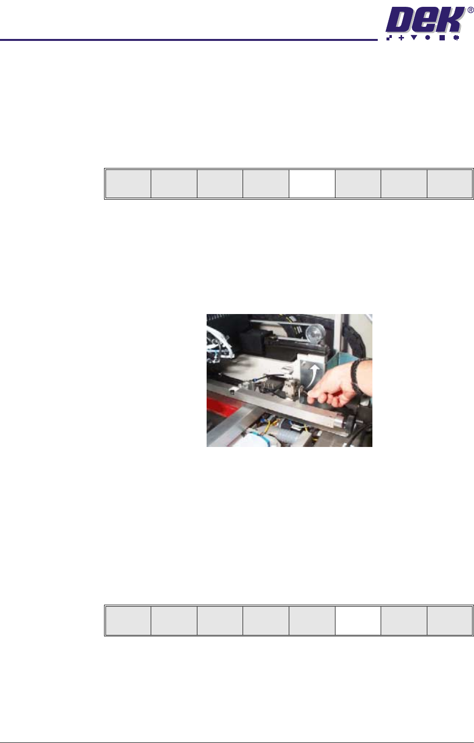
8. Either:
a. Open the front printhead cover.
or
b. Raise the printhead shutter and lower the drop down panel.
9. If fitted, toggle screen clamp switch to up position (off).
10.Remove the stencil from the printer.
11.Either:
a. Close the front printhead cover.
or
b. Raise the drop down panel and lower the printhead shutter.
12.Press the System button.
13.Select Change Tooling (F6). The print carriage and the under screen
cleaner are moved to the rear.
Mode
Load
Data
Edit
Data
Setup
Squeegee
Change
Screen
Change
Tool ing
Change
language
Exit
Mode
Load
Data
Edit
Data
Setup
Squeegee
Change
Screen
Change
Tooling
Change
Language
Exit
0$&+,1(352*5$00,1*
67$*('08/7,)/(;722/,1*
Software Version 07SP04 User Manual 1.45
The Change Tooling Parameters window is displayed:
NOTE
If the remote board stop is fitted the Board Stop X and Board Stop Y
parameters are replaced by Remote Board Stop X.
14.Setting up the board stop position is automatically done using the board
dimensions previously set in the product file. If they need adjustment to re-
position the board stop for any reason, ie any routing on the board edge or
a badly positioned image on the stencil, this can be done now. If adjustment
is necessary continue with Step 14. If adjustment is not necessary go to
Step 19.
15.Select Adjust (F1).
16.Use the Next and Previous keys (F4 - F5) to highlight each parameter.
17.Use the Incr. and Decr. keys (F6 - F7), or the forward slash key (/) on the
keyboard, to change the parameter value.
18.Select Save (F2). The message ‘Saving fiducial data - Please wait Board
data file saved’ is displayed.
19.Select Exit (F8).
20.Select Full Width (F5). The message ‘Checking for a board on the belts’
is displayed. Whilst the rear rail is moving the message ‘Rail moving...’ is
displayed.
Change Tooling Parameters
BOARD WIDTH
BOARD STOP X
BOARD STOP Y
UNDER CLEARANCE
216.0
125.0
142.6
19.0
mm
mm
mm
mm
Adjust
Open
Cover
Home
Cleaner
Board
Stop
Full
Width
Load
Width
Generic
Tool ing
Exit
Save Next Previous Incr. Decr. Exit
Save Next Previous Incr. Decr. Exit
Save Next Previous Incr. Decr. Exit
Save Next Previous Incr. Decr. Exit
Adjust
Open
Cover
Home
Cleaner
Board
Stop
Full
Width
Load
Width
Generic
Tool ing
Exit