Printer 600 Machine Programming.pdf - 第48页
0$&+,1( 352*5$00 ,1* 67$*(' 08/7,)/( ;722/,1* 1.48 User Manual Software Ve rsion 07SP04 The following windo w and menu bar is displayed: 35. Select Continue (F1). The mess age ‘ T able at Cont act Height.…
0$&+,1(352*5$00,1*
67$*('08/7,)/(;722/,1*
Software Version 07SP04 User Manual 1.47
The following window and menu bar is displayed:
NOTE
If contaminated squeegees are fitted, these should be replaced at this point.
28.Select Continue (F1). Cleaner moves to the Home position and the print
carriage moves to the rear of the machine. The message ‘Table at Home
Height’ is displayed.
29.Select Transprt Height (F3). The message ‘Table at Transport Height’ is
displayed.
30.Place a board on the input sensor of the upline conveyor of the machine.
31.Select Load (F1).
32.Select Auto Board (F1).
33.Select Vision Height (F3). The message ‘Table at Vision Height. Check
Tooling Clearance’ is displayed.
34.Select Contact Height (F3).
Generic Tooling Warning
WARNING Paste may drip into the machine
Remove Squeegees NOW
Continue
Open
Cover
Exit
Continue
Open
Cover
Exit
Load
Transprt
Height
Board
Clamps
Change
Screen
Open
Cover
Exit
Load
Vision
Height
Home
Height
Board
Clamps
Change
Screen
Open
Cover
Exit
Auto
Board
Manual
Board
Unload
Vision
Height
Home
Height
Board
Clamps
Change
Screen
Open
Cover
Exit
Contact
Height
Tra nspr t
Height
Change
Screen
Open
Cover
Exit
0$&+,1(352*5$00,1*
67$*('08/7,)/(;722/,1*
1.48 User Manual Software Version 07SP04
The following window and menu bar is displayed:
35.Select Continue (F1). The message ‘Table at Contact Height. Check
Tooling Clearance’ is displayed.
36.Select Open Cover (F7).
37.Either:
a. Open the front printhead cover.
or
b. Raise the printhead shutter.
38.Check that the setup of the tooling is adequate for the board, adjust as
necessary.
NOTE
If adjustment is required, this can be carried out at Transport Height.
39.Either:
a. Close the front printhead cover.
or
b. Lower the printhead shutter.
40.Press the System button.
41.Select Exit (F8).
42.Select Exit (F8).
Contact Height Warning
WARNING Check for obstructions between
the Rails and the Screen
Continue
Open
Cover
Exit
Continue
Open
Cover
Exit
Vision
Height
Open
Cover
Exit
Exit
Vision
Height
Open
Cover
Exit
0$&+,1(352*5$00,1*
67$*('08/7,)/(;722/,1*
Software Version 07SP04 User Manual 1.49
The following window and menu bar is displayed:
43.Select Continue (F1).
44.Select Auto Board (F1). The message ‘Board on rails, remove and
continue’ is displayed.
45.Remove the board from the rails.
46.Select Continue (F1).
47.Either:
a. Open the front printhead cover.
or
b. Raise the printhead shutter and lower the drop down panel.
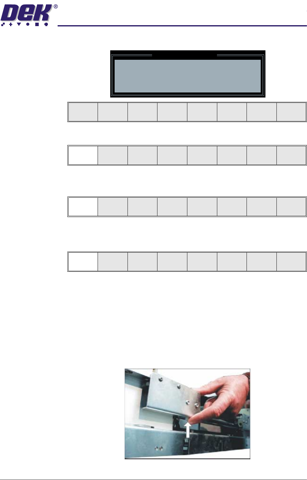
48.To adjust the width of the chase rails to accommodate the stencil for the
product file loaded, carry out the following (ASM only):
a. Press and hold the left hand chase rail push button valve.
b. Slide the left hand chase rail to the desired position indicated on the
Leaving Generic Tooling
WARNING You are about to return
to the Setup Page
Clear all tooling setup
equipment before proceeding
Continue Exit
Continue Exit
Auto
Board
Manual
Board
Continue
Open
Cover