Printer 600 Machine Programming.pdf - 第55页
0$&+,1 (352*5$0 0,1* 67$*( ()250 )/(;722/,1* Software Version 07SP04 User Manual 1.55 21. Select Open Cover (F7). 22. Either: a. Open the front prin thead cover . or b. Raise the printhead shut ter . 23. Using…
0$&+,1(352*5$00,1*
67$*(()250)/(;722/,1*
1.54 User Manual Software Version 07SP04
14.Select Exit (F8).
15.Select Generic Tooling (F7). The print carriage moves to the front of the
machine.
The following window and menu bar is displayed:
NOTE
If contaminated squeegees are fitted, these should be replaced at this point.
16.Select Continue (F1). Cleaner moves to the Home position and the print
carriage moves to the rear of the machine. The message ‘Table at Home
Height’ is displayed.
17.Select Transprt Height (F3). The message ‘Table at Transport Height’ is
displayed.
18.Place a board on the input sensor of the upline conveyor of the machine.
19.Select Load (F1).
20.Select Auto Board (F1).
Save Next Previous Incr. Decr. Exit
Adjust
Open
Cover
Home
Cleaner
Board
Stop
Full
Width
Load
Width
Generic
Tooling
Exit
Generic Tooling Warning
WARNING Paste may drip into the machine
Remove Squeegees NOW
Continue
Open
Cover
Exit
Continue
Open
Cover
Exit
Load
Transprt
Height
Board
Clamps
Change
Screen
Open
Cover
Exit
Load
Vision
Height
Home
Height
Board
Clamps
Change
Screen
Open
Cover
Exit
Auto
Board
Manual
Board
0$&+,1(352*5$00,1*
67$*(()250)/(;722/,1*
Software Version 07SP04 User Manual 1.55
21.Select Open Cover (F7).
22.Either:
a. Open the front printhead cover.
or
b. Raise the printhead shutter.
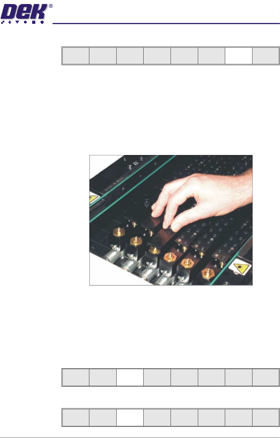
23.Using the board on the rails as a template, slide the appropriate size and
number of FormFlex blanking plates on to the tooling modules outside the
area of the squeegees/ProFlow transfer head. Secure the plates using the
thumbscrews.
24.Either:
a. Close the front printhead cover.
or
b. Lower the printhead shutter.
25.Press the System button.
26.Select Vision Height (F3). The message ‘Table at Vision Height. Check
Tooling Clearance’ is displayed.
27.Select Contact Height (F3).
Unload
Vision
Height
Home
Height
Board
Clamps
Change
Screen
Open
Cover
Exit
Unload
Vision
Height
Home
Height
Board
Clamps
Change
Screen
Open
Cover
Exit
Contact
Height
Tra nspr t
Height
Change
Screen
Open
Cover
Exit
0$&+,1(352*5$00,1*
67$*(()250)/(;722/,1*
1.56 User Manual Software Version 07SP04
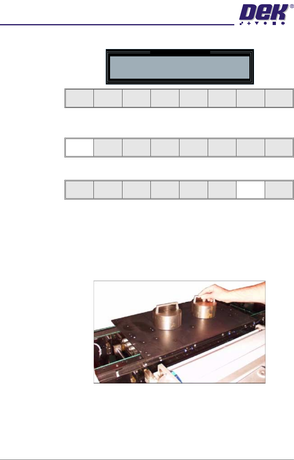
The following window and menu bar is displayed:
28.Select Continue (F1). The message ‘Table at Contact Height. Check
Tooling Clearance’ is displayed.
29.Select Open Cover (F7).
30.Either:
a. Open the front printhead cover.
or
b. Raise the printhead shutter.
31.Place the FormFlex setup plate centrally over the tooling modules and rails
and place the weights on top of the setup plate.
32.Align the weights along the centre line in the Y axis and one third of the plate
Contact Height Warning
WARNING Check for obstructions between
the Rails and the Screen
Continue
Open
Cover
Exit
Continue
Open
Cover
Exit
Vision
Height
Open
Cover
Exit