Printer 600 Machine Programming.pdf - 第70页
0$&+,1( 352*5$00 ,1* 67$*( 9,6,216 <67(06 (783 1.70 User Manual Software Ve rsion 07SP04 ST AGE 6 - VISION SYSTEM SETUP Introduct ion The machine utilize s a vi sion syst em to ca rry ou t the followi ng: …
0$&+,1(352*5$00,1*
67$*(()250)/(;722/,1*
Software Version 07SP04 User Manual 1.69
47.Select Change Screen (F5).
48.Either:
a. Open the front printhead cover.
or
b. Raise the printhead shutter and lower the drop down panel.
49.If fitted, toggle screen clamp switch to up position (off).
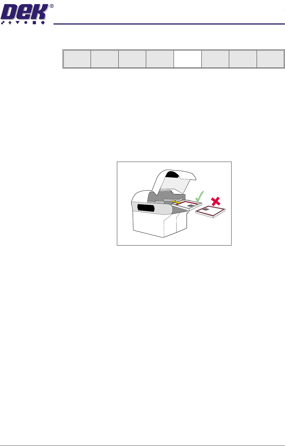
50.Remove the screen from the printer and release the universal set plate from
the screen.
51.Ensuring correct orientation, refit the screen
52.If fitted, toggle screen clamp switch to down position (on).
53.Either:
a. Close the front printhead cover.
or
b. Raise the drop down panel and lower the printhead shutter.
54.Press the System button.
55.Go to Stage 6.
Mode
Load
Data
Edit
Data
Setup
Squeegee
Change
Screen
Change
Tool ing
Change
Language
Exit

0$&+,1(352*5$00,1*
67$*(9,6,216<67(06(783
1.70 User Manual Software Version 07SP04
STAGE 6 - VISION SYSTEM SETUP
Introduction The machine utilizes a vision system to carry out the following:
• Stencil/Board Alignment
• 2D Inspection (optional)
• Board Identification - Selective Print/Pass Through (optional)
Once a board is fed into the machine to the board stop position, the camera
moves into position to view the relative board and stencil features. The camera
image information is used by the vision system to calculate if stencil correction
is needed and if selective print/pass through is enabled, to identify the board.
The camera and vision system is also used for 2D Inspection (2Di), if enabled.
For further information on 2Di, refer to the 2Di chapter of this manual.
Fiducials Fiducials are alignment marks produced as a part of the artwork of the board
and the stencil. Normally, several fiducials can be found on each board, some
of which are used for board alignment and some for alignment when placing
components on the board. These fiducials, should therefore be in the same
relative position on both board and stencil.
The vision system has a library of synthetic fiducials of the most commonly
found shapes. The dimensions of these fiducials can be tailored by the operator
to fit the fiducials on the board and stencil. After the vision system has been
taught these fiducial parameters, it is able to search the field of view of the
camera and recognize any features which resemble these fiducials. The centre
of the fiducial is calculated and used as the point of location.
After finding a shape it is assigned a score comparing its shape and size to the
shape and size of the fiducial in the vision system memory. This score is set
between 1 and 999, the better the fit the higher the score.
NOTE
This however, does not mean that a fiducial score of 999 for example, aligns
more accurately than a fiducial score of 700.
This score is used, in conjunction with acceptance parameters set by the
operator, to recognize the fiducial. The available fiducial shapes are:
• Circle
• Cross
• Diamond
• Triangle
• Rectangle
• Double Square
Circle
Cross
Diamond
Triangle Rectangle Double square
0$&+,1(352*5$00,1*
67$*(9,6,216<67(06(783
Software Version 07SP04 User Manual 1.71
Fiducial
Parameters
A number of parameter values are required to be adjusted when setting up a
fiducial.
Fiducial Type This refers to the shape and dimensions of the fiducial.
Background The vision system needs to know if the fiducial is surrounded by a dark or light
background compared to the fiducial colour.
Acceptance Score After the vision system has located a stencil or board fiducial, it is then given a
level of match for that fiducial compared to the fiducial programmed in the vision
system. This match level is assigned a score, the better the match the higher
the score. The acceptance score is set by the operator as the minimum level,
above this minimum level the vision system accepts the recognition of the
fiducial.
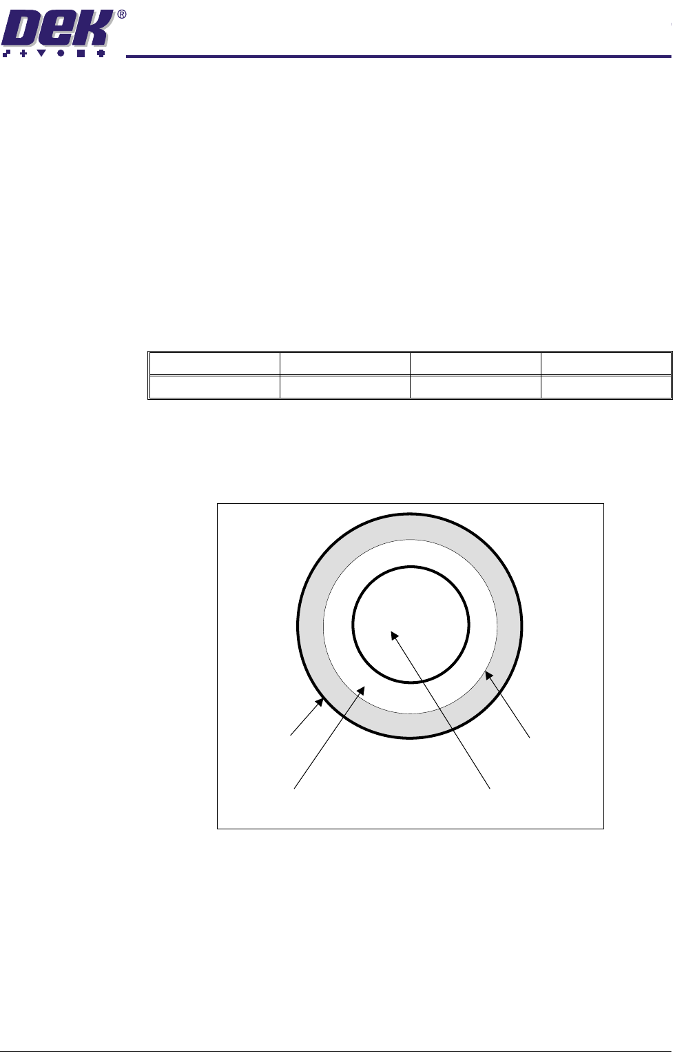
There are various dimensions of each fiducial shape which have to be set by
the operator. The figure below describes a circular example portraying these
various dimensions.
Fiducial Diameter This needs to be set to the diameter of the fiducial to achieve a satisfactory
score.
Inner and Outer
Contours
These are set to eliminate any defects that may occur in the surface of either
the fiducial or the background. The vision system ignores anything inside the
inner contour and outside the outer contour. Increasing the distance between
the inner and outer contour can, if the fiducial and background surfaces are
variable, drastically affect the score level.
Minimum Maximum Increment Default
0 999 10 700
Outer Contour
Inner Contour
Geometric Centre
(used as a location point)
Fiducial Diameter