Oxford-100-ICP-2-Step-DRIE-SOP-in-PDF-Format.pdf - 第3页
Oxford ICP 2 - step DRIE SOP Page 3 of 10 Revisi on 2- 12 0 321 4. Equipm ent and/o r Mater ials 4.1 Wafer/S ample 4.2 Oxford 100 4.3 Liquid N itrogen 5. Saf ety 5.1 Follow al l Nanof ab saf ety pro cedures . 6. Setup P …

Oxford ICP 2-step DRIE SOP Page 2 of 10
Revision 2-120321
1. Scope
1.1 This document provides operating procedures for the Oxford 100 ICP 2-step DRIE.
2. Table of Contents
1. Scope ............................................................................................................................................................. 2
2. Table of Contents .......................................................................................................................................... 2
3. Reference Documents ................................................................................................................................... 2
3.1 Referenced within this Document .......................................................................................................... 2
3.2 External Documents ............................................................................................................................... 2
4. Equipment and/or Materials ......................................................................................................................... 3
5. Safety............................................................................................................................................................. 3
6. Setup Procedures .......................................................................................................................................... 3
6.1 Reserve and Enable tool in Coral ............................................................................................................ 3
6.3 Vent Load Lock ........................................................................................................................................ 4
5
6.4 Load Wafer ............................................................................................................................................. 5
7. Run Recipe..................................................................................................................................................... 5
7.1 Load and Edit Recipe .............................................................................................................................. 5
7.2 Start Etch Process ................................................................................................................................... 7
8. Shutdown Procedures ................................................................................................................................... 8
8.1 Vent Load Lock ........................................................................................................................................ 8
8.2 Shutdown System ................................................................................................................................... 8
9. Revision History ........................................................................................................................................... 10
Figure 1, Liquid Nitrogen Tank .................................................................................... Error! Bookmark not defined.
Figure 2, Chiller ........................................................................................................... Error! Bookmark not defined.
Figure 3, Pump Control Page ...................................................................................................................................... 5
Figure 4, Load Lock ..................................................................................................................................................... 5
Figure 5, Temperature Controller .............................................................................................................................. 4
Figure 6, Recipe Editor Page ...................................................................................................................................... 6
Figure 7, Process Control Page ................................................................................................................................... 8
Figure 8, Etch Rate for 10 um Trenches ...................................................................... Error! Bookmark not defined.
Figure 9, Etch Rate for 2 um Trenches ........................................................................ Error! Bookmark not defined.
Figure 10, Etch Rate for 4 um Pillars ........................................................................... Error! Bookmark not defined.
Figure 11, 2-step Etching SEM Analysis ....................................................................... Error! Bookmark not defined.
Table 1, Deep Etch Recipe ......................................................................................................................................... 7
Table 2, Smooth Etch Recipe ...................................................................................... Error! Bookmark not defined.
3. Reference Documents
3.1 Referenced within this Document
3.2 External Documents
3.2.1 None
Oxford ICP 2-step DRIE SOP Page 3 of 10
Revision 2-120321
4. Equipment and/or Materials
4.1 Wafer/Sample
4.2 Oxford 100
4.3 Liquid Nitrogen
5. Safety
5.1 Follow all Nanofab safety procedures.
6. Setup Procedures
6.1 Reserve and Enable tool in Coral
6.1.1 Etch-Oxford 100 DRIE (software Login is nanofabuser, pw nanofabuser)
6.1.2 Record all processing and characterization information in Coral
6.2 Set chuck temperature
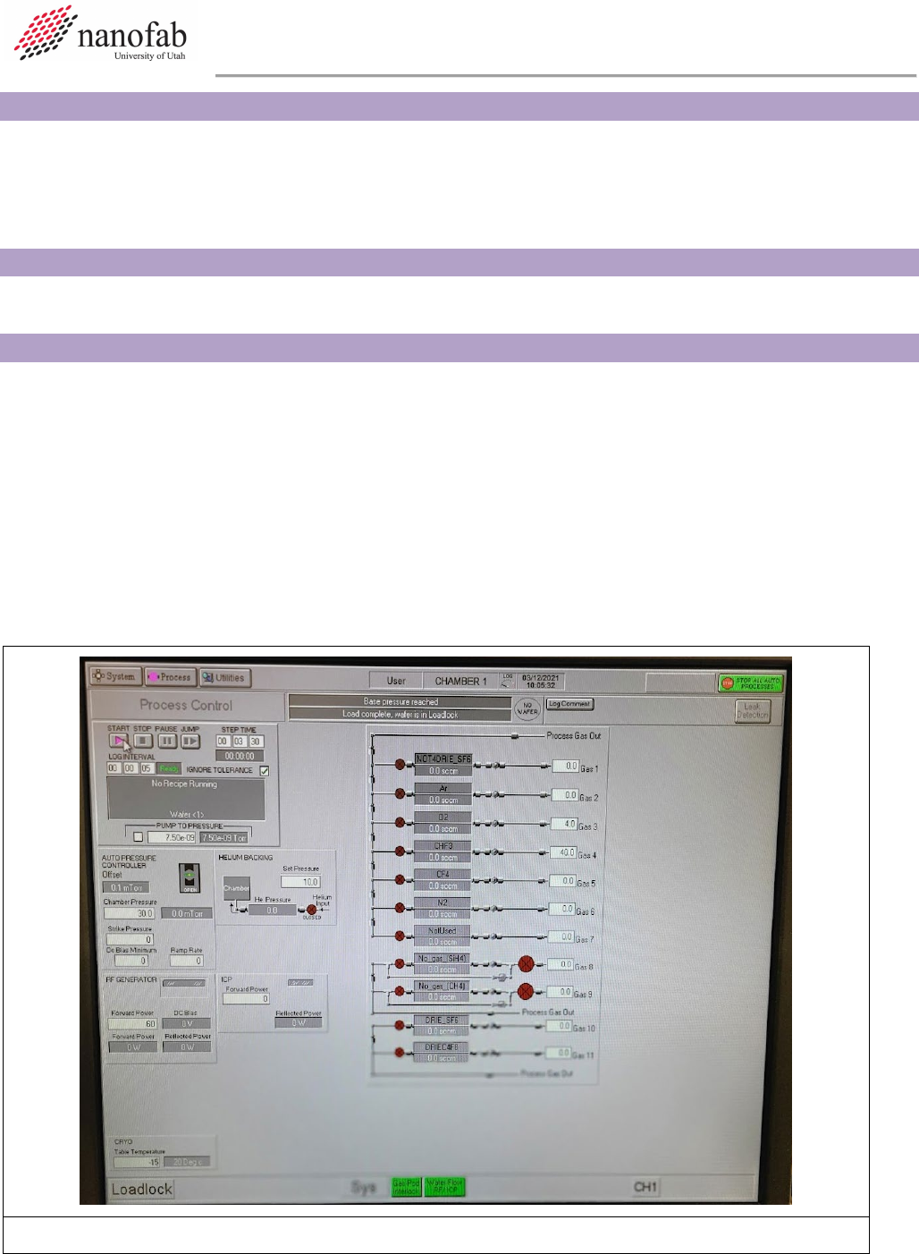
6.2.1 Click on Process icon. See Figure 1, Pump Control Page.
6.2.2 Click on “Chamber 1” on the drop-down menu
6.2.3 Set the table temperature to -15 (lower left corner of screen) See Figure 1.
6.2.4 Press the pink start button, then immediately click stop (right next to it). See Figure 1.
Figure 1. Set Chuck Temperature
Oxford ICP 2-step DRIE SOP Page 4 of 10
Revision 2-120321
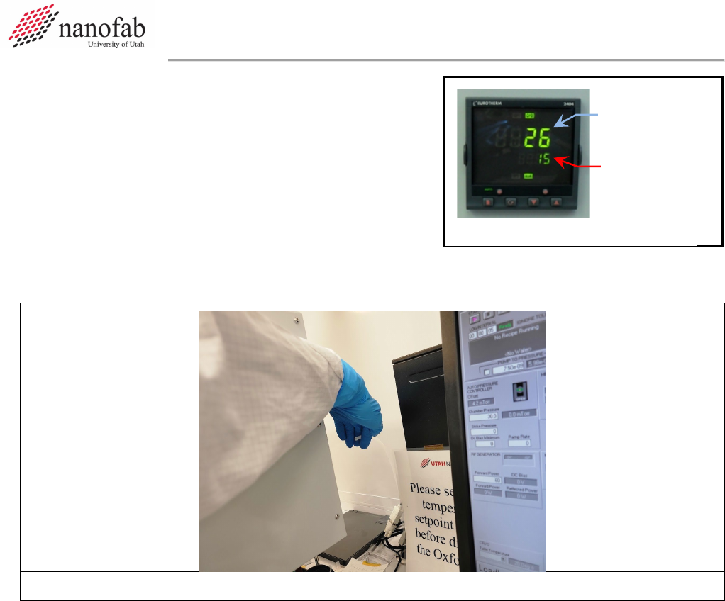
6.2.5 Check the set point on the temperature controller to
make sure the set point number reads -15 (see
Figure 2). The controller won’t function unless you
initially set it way below your desired set point, and
then change it to the actual set point later.
6.2.6 Find the unattached tube behind the main chamber. Feel the output to make sure nitrogen is
flowing out of it (see Fig 3). This means the chuck is being cooled to the setpoint.
Figure 3. N2 cooling flow tube
6.2.7 Now set the table temperature to your desired setpoint (typically 15C for most DRIE Bosch
recipes) (lower left corner of screen) See Figure 1.
6.2.8 Press the pink start button, then immediately click stop (right next to it). See Figure 1.
6.2.9 Find the unattached tube behind the main chamber. Feel the output to make sure nitrogen is
still flowing out of it.
6.3 Vent Load Lock
6.3.1 Click on System icon. See Figure 4 Pump Control Page.
6.3.2 Click on “pumping” on the drop-down menu
6.3.3 Press stop button corresponding to the load lock mechanical pump (on the left side of the
screen, do not touch the main chamber buttons on the right side of the screen). See Figure 4.
6.3.4 Press stop, then ok, then vent, then ok buttons. See Figure 1.
6.3.5 Wait for load lock to vent. The pressure will read above 600 Torr and you will hear hissing
initially from the load lock lid.
Set point
Actual
Temperature
Figure 2, Temperature Controller