Oxford-100-ICP-2-Step-DRIE-SOP-in-PDF-Format.pdf - 第4页
Oxford ICP 2 - step DRIE SOP Page 4 of 10 Revisi on 2- 12 0 321 6.2.5 Check the set point on the tempe rature contr oller to make sure the set point number reads -15 (see Figure 2). The controller won’t function unless y…
Oxford ICP 2-step DRIE SOP Page 3 of 10
Revision 2-120321
4. Equipment and/or Materials
4.1 Wafer/Sample
4.2 Oxford 100
4.3 Liquid Nitrogen
5. Safety
5.1 Follow all Nanofab safety procedures.
6. Setup Procedures
6.1 Reserve and Enable tool in Coral
6.1.1 Etch-Oxford 100 DRIE (software Login is nanofabuser, pw nanofabuser)
6.1.2 Record all processing and characterization information in Coral
6.2 Set chuck temperature
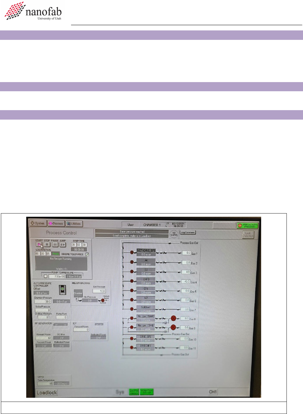
6.2.1 Click on Process icon. See Figure 1, Pump Control Page.
6.2.2 Click on “Chamber 1” on the drop-down menu
6.2.3 Set the table temperature to -15 (lower left corner of screen) See Figure 1.
6.2.4 Press the pink start button, then immediately click stop (right next to it). See Figure 1.
Figure 1. Set Chuck Temperature
Oxford ICP 2-step DRIE SOP Page 4 of 10
Revision 2-120321
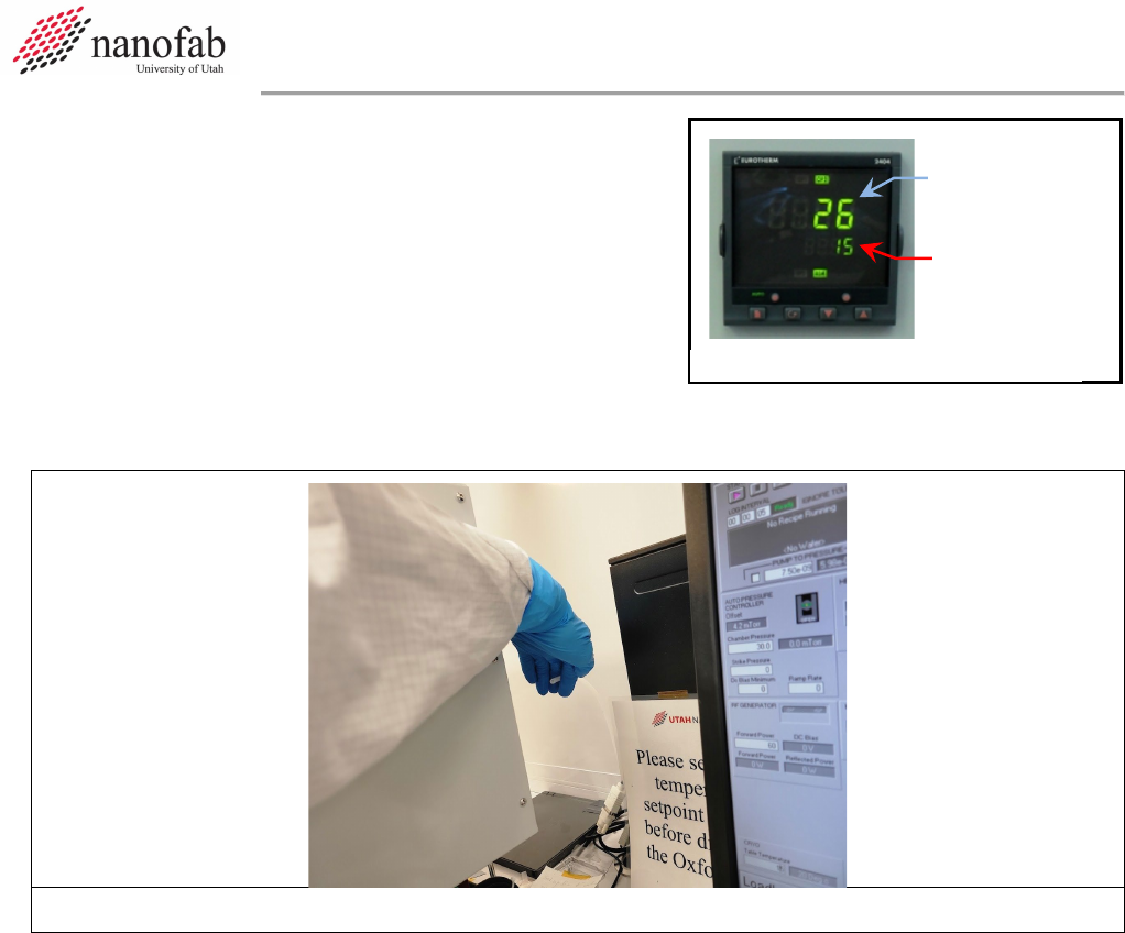
6.2.5 Check the set point on the temperature controller to
make sure the set point number reads -15 (see
Figure 2). The controller won’t function unless you
initially set it way below your desired set point, and
then change it to the actual set point later.
6.2.6 Find the unattached tube behind the main chamber. Feel the output to make sure nitrogen is
flowing out of it (see Fig 3). This means the chuck is being cooled to the setpoint.
Figure 3. N2 cooling flow tube
6.2.7 Now set the table temperature to your desired setpoint (typically 15C for most DRIE Bosch
recipes) (lower left corner of screen) See Figure 1.
6.2.8 Press the pink start button, then immediately click stop (right next to it). See Figure 1.
6.2.9 Find the unattached tube behind the main chamber. Feel the output to make sure nitrogen is
still flowing out of it.
6.3 Vent Load Lock
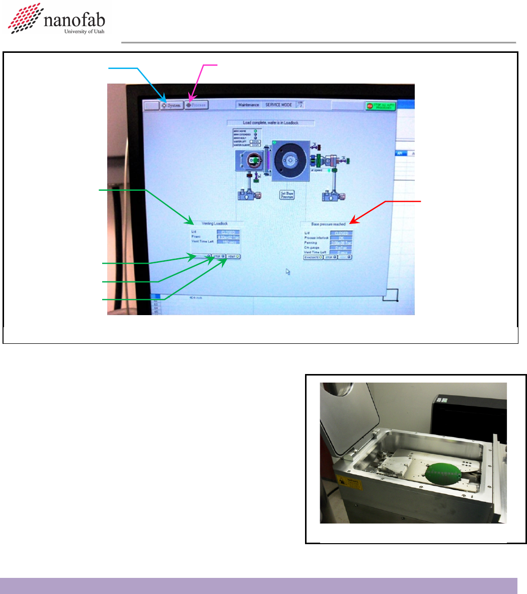
6.3.1 Click on System icon. See Figure 4 Pump Control Page.
6.3.2 Click on “pumping” on the drop-down menu
6.3.3 Press stop button corresponding to the load lock mechanical pump (on the left side of the
screen, do not touch the main chamber buttons on the right side of the screen). See Figure 4.
6.3.4 Press stop, then ok, then vent, then ok buttons. See Figure 1.
6.3.5 Wait for load lock to vent. The pressure will read above 600 Torr and you will hear hissing
initially from the load lock lid.
Set point
Actual
Temperature
Figure 2, Temperature Controller
Oxford ICP 2-step DRIE SOP Page 5 of 10
Revision 2-120321
6.3.6 Press stop button. See Figure 4.
6.4 Load Wafer
6.4.1 Open load lock lid (See Fig 5)
6.4.2 Place wafer in load lock against the two pins on
the transfer arm with the wafer facing the two
pins. The wafer should touch the two pins. See
Figure 5, Load Lock.
6.4.3 Close load lock lid.
7. Run Recipe
NOTE: This recipe can be used to etch deep trenches or vias in 100 mm wafers. It is strongly
advised that you do a test run on a practice wafer before working with your device wafer.
7.1 Load and Edit Recipe
7.1.1 Click on Process icon. See Figure 6, Pump Control Page.
7.1.2 Click on “Recipes” on the drop-down menu
Figure 5, Load Lock
System
Button
Process Buttton
Load Lock
Controls
Evacuate
Stop
Vent
Main
Chamber
Controls Do
Not Touch
Figure 4, Pump Control Page