00195044-10_UM_VisionTeachStation_DE EN.pdf - 第120页
5 Installing the cameras Vision Teach Station User Manual 5.1 Installing stationary cameras, type 25, 33 and 36 12/2012 Edition 120 5.1.1.3 Assembling the camera Slide the cover (item 2) nose-first into the base plate …
Vision Teach Station User Manual 5 Installing the cameras
12/2012 Edition 5.1 Installing stationary cameras, type 25, 33 and 36
119
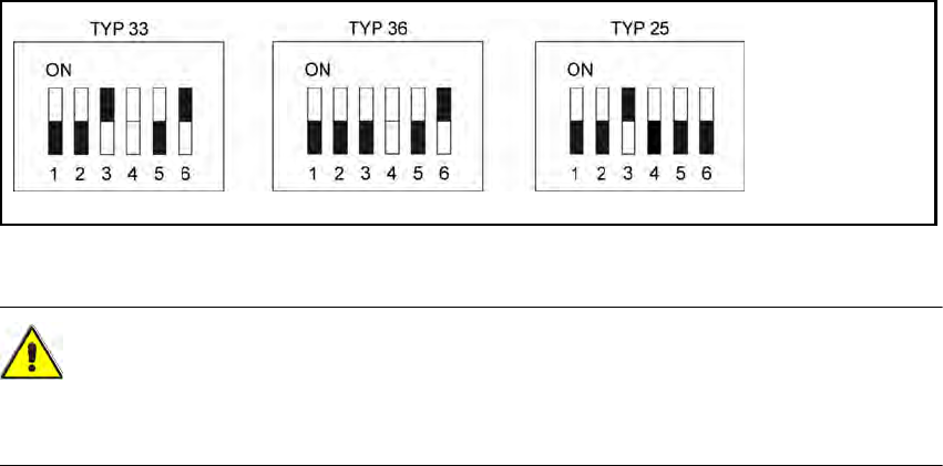
Fig. 5.1 - 4 DIP switch settings on the stationary cameras (version with 6 switches)
CAUTION 5
In the version with 6 switches, switch no. 4 must NOT be changed, as this might cause malfunc-
tion of the LED self test.
5
5 Installing the cameras Vision Teach Station User Manual
5.1 Installing stationary cameras, type 25, 33 and 36 12/2012 Edition
120
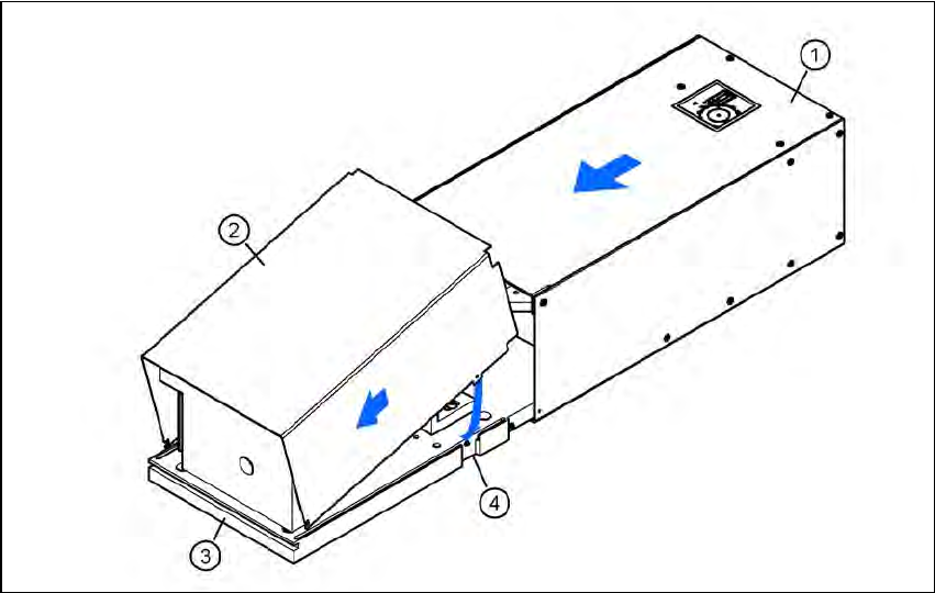
5.1.1.3 Assembling the camera
Slide the cover (item 2) nose-first into the base plate (item 3).
Swivel the cover down until it engages on the ball catch (item 4) in the base plate (item 3).
Slide the illumination head (item 1) back until it engages.
5
Fig. 5.1 - 5 Assembling the camera
Vision Teach Station User Manual 5 Installing the cameras
12/2012 Edition 5.1 Installing stationary cameras, type 25, 33 and 36
121
5.1.2 Installing the camera on the base module
5.1.2.1 Tools required
Allen key, set
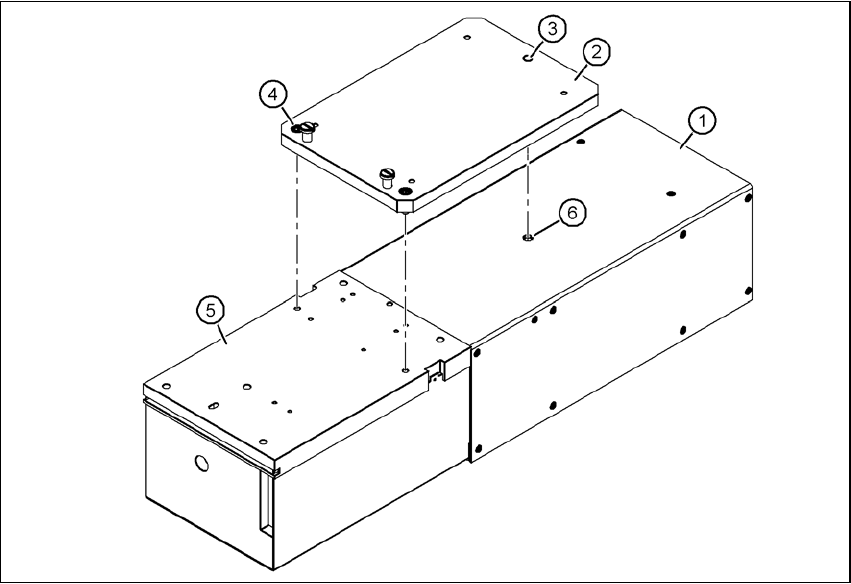
5.1.2.2 Fitting the mount for camera types 33, 36 and 25
Turn the camera 180° about its long axis so that the base plate (item 5) is pointing up.
Place the mount (item 2) on the camera so that the parallel pin (item 3) slides into the hole (item
6) in the illumination head (item 1).
Fix the mount (item 2) to the base plate (item 5) using the two hexagon socket head screws
M6 x 16 (item 4).
The illumination head can no longer become detached from the base module.
5
Fig. 5.1 - 6 Fitting the mount for camera type 33
(1) Illumination head
(2) Mount for type 33/36, item no. 03039467-xx; mount for type 25, item no. 03039471-xx
(3) Parallel pin
(4) Hexagon socket head screw M6 x 12, 2x
(5) Base plate
(6) Hole for parallel pin