00195044-10_UM_VisionTeachStation_DE EN.pdf - 第128页
5 Installing the cameras Vision Teach Station User Manual 5.2 Installing head cameras, type 28, 29 and 30 12/2012 Edition 128 5 Fig. 5.2 - 9 Running the cables for the camera type SST 28/29 and 23 (1) Wire management mou…
Vision Teach Station User Manual 5 Installing the cameras
12/2012 Edition 5.2 Installing head cameras, type 28, 29 and 30
127
5.2.3 Running the cables
Fix the head camera adapter (item 4 in Fig. 5.2 - 9, page 128) to the pillar (item 20 in Fig. 5.2
- 9, page 128). The adapter should be attached roughly level with the cable exit from the com-
ponent camera.
Loosen the two cable clamps on the adapter and one on the back of the base module.
WARNING 5
Always make sure that the base module is switched off when you connect or remove con-
nectors.
NEVER unplug the 26-pin cable while it is carrying voltage. as this could damage the LED
driver board for the camera. 5
CAUTION 5
– Make sure that the connectors are attached straight to avoid damaging them. The connectors
have claws on the side to prevent them working loose accidentally.
– When you release the plug-in connection, first press down on the claw lever, then remove the
connector.
– Do not pull on the cable to release the connector.
First plug the 12-pin camera cable into the adapter, then the 26-pin cable.
Secure the cables with cable clamps on the adapter.
Do the same for the 03040353 extension cable.
Connect the 03040353 extension cable to one of the two head camera terminals (item 8 in Fig.
5.2 - 10, page 129) and to the back of the base module .
Fix the extension cable.
To do this, press the two expanding nuts (the small, black cubes with threaded hole) into the
groove in the pillar beneath the cable.
Screw a wire management mount (item 1 in Fig. 5.2 - 9, page 128 onto each nut).
Fix the cable using cable ties.
5 Installing the cameras Vision Teach Station User Manual
5.2 Installing head cameras, type 28, 29 and 30 12/2012 Edition
128
5
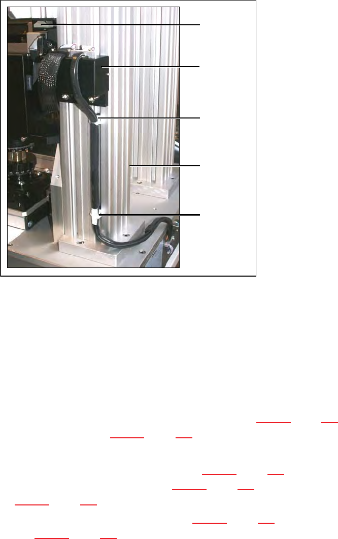
Fig. 5.2 - 9 Running the cables for the camera type SST 28/29 and 23
(1) Wire management mount
(2) Pillar
(3) Wire management mount on camera type 29
(4) Adapter for head camera
5.2.4 Fitting the component support
Release the lock on the positioning unit (item 2 in Fig. 5.2 - 10, page 129) using the magnetic
switch (item 1 in Fig. 5.2 - 10, page 129)
Push the positioning unit out.
Fix the component support (item 5 in Fig. 5.2 - 10, page 129) using the two hexagon socket
head screws M3 x 8 (item 4 in Fig. 5.2 - 10, page 129) to the holder (item 3 in Fig.
5.2 - 10, page 129).
Push the positioning unit (item 2 in Fig. 5.2 - 10, page 129) back towards the pillar (item 6 in
Fig. 5.2 - 10, page 129) and lock the positioning unit in place.
(1)
5
(2)
5
(1)
(3)
5
(4)
Vision Teach Station User Manual 5 Installing the cameras
12/2012 Edition 5.2 Installing head cameras, type 28, 29 and 30
129
5
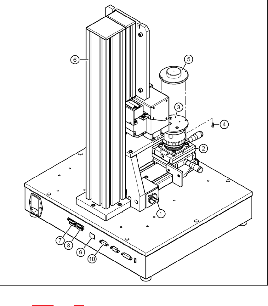
Fig. 5.2 - 10 Base module with camera type 28
Key to fig. 5.2 - 10, page 129
(1) Magnetic switch
(2) Positioning unit
(3) Holder for component support
(4) Hexagon socket head screw M3 x 8, 2x
(5) Component support, camera type 28/29
(6) Pillar