00195044-10_UM_VisionTeachStation_DE EN.pdf - 第131页
Vision Teach Station User Manual 5 Installing the cameras 12/2012 Edition 5.3 Installing the type 23 head camera 131 5.3 Installing the type 23 head camera The type 23 head camera is the component camera for the 20-segme…

5 Installing the cameras Vision Teach Station User Manual
5.2 Installing head cameras, type 28, 29 and 30 12/2012 Edition
130
(7) Connection for cable, head camera 1 (03040353-W1: 26-pin, 03040353-W2: 12-pin)
(8) Connection for cable, head camera 2 (03040353-W1: 26-pin, 03040353-W2: 12-pin)
(9) Connection for camera bus cable to the PC (03040359-xx)
(10)Connection for CAN bus cable to the PC (03040362-xx)
5.2.5 Connecting the adapter, base module and PC
Connect the camera bus connection on the base module (item 9 in Fig. 5.2 - 10, page 129) to
the card for the camera bus interface in the PC (item 1 in Fig. 4.3 - 2, page 115) with the cable
03040359-xx.
Connect the CAN bus connection on the base module (item 10 in Fig. 5.2 - 10, page 129) to
the interface card in the PC (item 2 in Fig. 4.3 - 2, page 115) with cable 03040362-xx.

Vision Teach Station User Manual 5 Installing the cameras
12/2012 Edition 5.3 Installing the type 23 head camera
131
5.3 Installing the type 23 head camera
The type 23 head camera is the component camera for the 20-segment Collect&Place head.
5.3.1 Tools required
Allen key, set
5.3.2 Fitting camera type 23 to the mounting plate
Fit the mount (item 3 in Fig. 5.3 - 11, page 132) to the mounting plate (item 7 in Fig. 5.3 - 11,
page 132) using the two hexagon socket head screws M6 x 12 (item 4 in Fig. 5.3 - 11, page
132).
Place the camera (item 1 in Fig. 5.3 - 11, page 132) on the mount (item 3 in Fig. 5.3 - 11, page
132) so that the two parallel pins of the camera slide into the holes in the mounting plate and
so that the camera lies flat on the mounting plate.
Use the four hexagon socket head screws M3 x 12 (item 2 in Fig. 5.3 - 11, page 132) to fit the
component camera (item 4 in Fig. 5.3 - 11, page 132).
5 Installing the cameras Vision Teach Station User Manual
5.3 Installing the type 23 head camera 12/2012 Edition
132
5
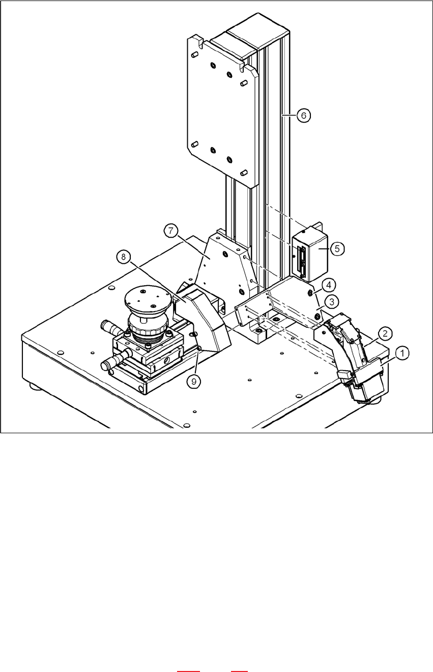
Fig. 5.3 - 11 Installing camera type 23
(1) Camera type 23
(2) Hexagon socket head screw M3 x 12, 4x
(3) Mount for camera type 23
(4) Hexagon socket head screw M6 x 12, 2x
(5) Adapter for head camera
(6) Pillar
(7) "Bottom" mounting plate"
(8) Cover for camera type 23
(9) Hexagon socket head screw M4 x 8, 2x
5.3.3 Running the cables
Run the cables as described in section 5.2.3, page 127.