00195044-10_UM_VisionTeachStation_DE EN.pdf - 第134页
5 Installing the cameras Vision Teach Station User Manual 5.3 Installing the type 23 head camera 12/2012 Edition 134 (8) Connection for cable, head camera 2 (03040353-W1: 26-pin, 03040353-W2: 12-pin) (9) Connection for c…
Vision Teach Station User Manual 5 Installing the cameras
12/2012 Edition 5.3 Installing the type 23 head camera
133
5.3.4 Fitting the component support
5
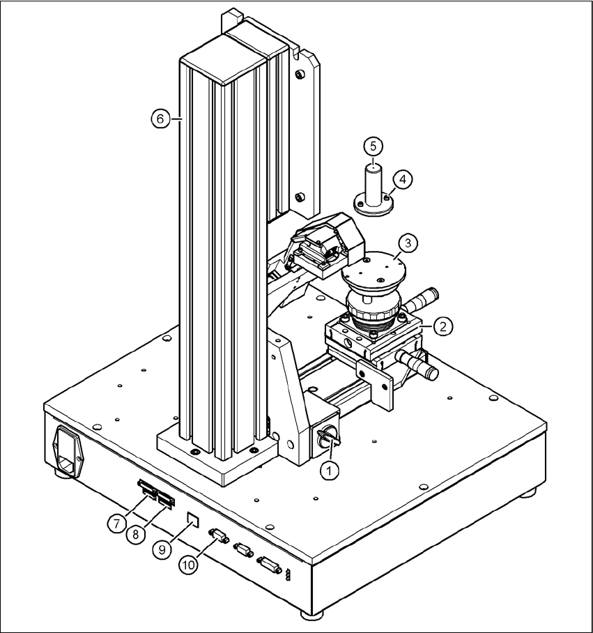
Fig. 5.3 - 12 Base module with camera type 23
(1) Magnetic switch
(2) Positioning unit
(3) Holder for component support
(4) Hexagon socket head screw M3 x 10, 2x
(5) Component support, camera type 23
(6) Pillar
(7) Connection for cable, head camera 1 (03040353-W1: 26-pin, 03040353-W2: 12-pin)

5 Installing the cameras Vision Teach Station User Manual
5.3 Installing the type 23 head camera 12/2012 Edition
134
(8) Connection for cable, head camera 2 (03040353-W1: 26-pin, 03040353-W2: 12-pin)
(9) Connection for camera bus cable to the PC (03040359-xx)
(10)Connection for CAN bus cable to the PC (03040362-xx)
Release the lock on the positioning unit (item 2 in Fig. 5.3 - 12, page 133) using the magnetic
switch (item 1 in Fig. 5.3 - 12, page 133)
Push the positioning unit out.
Fix the component support (item 5 in Fig. 5.3 - 12, page 133) using the two hexagon socket
head screws M3 x 10 (item 4 in Fig. 5.3 - 12, page 133) to the holder (item 3 in Fig.
5.3 - 12, page 133).
Push the positioning unit (item 2 in Fig. 5.3 - 12, page 133) back towards the pillar (item 6 in
Fig. 5.3 - 12, page 133) and lock the positioning unit in place.
WARNING 5
Always make sure that the base module and PC are switched off when you connect or re-
move connectors.
NEVER unplug the 26-pin ribbon cable while it is carrying voltage as this could damage the
LED driver board for the camera. 5
5.3.5 Connecting the adapter, base module and PC
Run the cables as described in section 5.2.5, page 130.

Vision Teach Station User Manual 6 2nd camera option
12/2012 Edition 6.1 Vision teach station upgrade
135
6 2nd camera option
You can install a second camera on the vision teach station as an option. We can provide the up-
grade package you will need. This package does NOT include the camera and assembly kit, how-
ever, which should be ordered separately.
6.1 Vision teach station upgrade
6.1.1 Bill of materials
6.1.2 Component camera
You will find the order data for the component cameras in section 3.2, page 104.
6.1.3 Assembly
When the vision teach station is converted to two cameras, the pillar and the component positio-
ning table are moved from the middle to the left (see Fig. 6.1 - 1, page 137). The additional pillar
and the component positioning table are fixed to the holes on the right-hand side. The conversion
is described in the enclosed assembly instructions.
Order designation
Item no.
Optional 2nd pillar for vision teach station
03063366-xx
Designation
Item no. Number
Vision teach station pillar
03039431-xx 1
Cable set for vision teach station
03040352-xx 1
Assembly instructions "Optional pillar for vision teach
station" 00196052-xx 1