00198505-01_SM_SIPLACE_SmartFeeder_EN.pdf - 第121页
7 Repairs to SmartFeeder 8 mm X 7.13 Foil disposal blade Service Manual SIPLACE SmartFeeder 4 - 104 mm X 11/2017 121 7.13 Foil disposal blade Required spare part Fig.37: Blade partition wall Feeder module Item no. Desig…
7 Repairs to SmartFeeder 8 mm X
7.12 Foil disposal flap
120 Service Manual SIPLACE SmartFeeder 4 - 104 mm X 11/2017
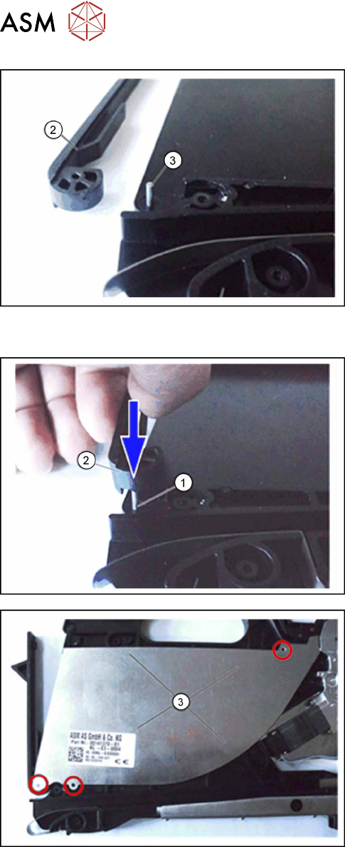
► Remove the flap(2) and the shaft(3). The shaft
is only pushed into the foil tank.
► Clean the foil tank thoroughly and remove all foil
and adhesive residues before fitting the foil tank
panel back on the foil tank.
7.12.2 Fitting the Flap
► Insert the shaft(1) into the foil tank for the feeder
module.
► Push the flap(2) onto the shaft.
► Place the foil tank panel(3) onto the foil tank, as
shown.
Make sure that the foil tank panel engages with
the nibs provided at the positions marked in red.
► Fit the right side cover (see7.3.4 "Fitting the right
side cover 8" [}85]).
7 Repairs to SmartFeeder 8 mm X
7.13 Foil disposal blade
Service Manual SIPLACE SmartFeeder 4 - 104 mm X 11/2017 121
7.13 Foil disposal blade
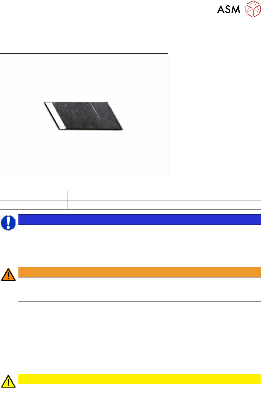
Required spare part
Fig.37: Blade partition wall
Feeder module Item no. Designation
SmartFeeder 8mmX 00341370Sxx Blade partition wall
NOTICE
Pay attention when preparing the individual blades. Individual blades must be broken at the
cutter edge. Ensure all safety precautions are observed.
Required tools
●
TORX screwdriver 0.6Nm, size T8
WARNING
Risk of injury
The edge of the blade is very sharp. Make sure that you always use a pair of tweezers
when removing and fitting the blade.
7.13.1 Removing the Blade Partition Wall
► Place the feeder on a stable, level and clean surface.
► Open the flap.
► Loosen the screw fastening the blade and remove the old blade.
7.13.2 Fitting the Blade Partition Wall
► Place the new blade in position and tighten the screw.
CAUTION
► The blades are sharp, take necessary safety precautions.
7 Repairs to SmartFeeder 8 mm X
7.14 Handle with control panel
122 Service Manual SIPLACE SmartFeeder 4 - 104 mm X 11/2017
7.14 Handle with control panel
7.14.1 Control Panel Assembly
Required spare part
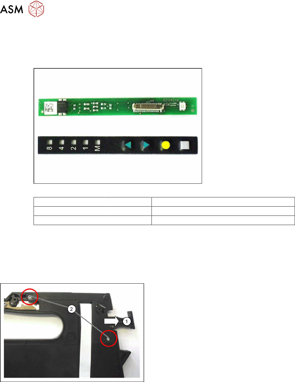
Fig.38: Board assy. control panel (top), control panel assy. (bottom)
Feeder module Item no. Designation
SmartFeeder 8mm X 03104269-xx Board assy. control panel X8Smart
SmartFeeder 8mm X 03102428 -xx Control panel assy. X8Smart
Required tools
●
Phillips screwdriver 0.9Nm
●
TORX screwdriver size T8, 0.6Nm
●
Tweezers or small screwdriver
7.14.1.1 Removing the Control Panel and Board
► Carefully place the feeder module with the right
side down on a stable, level and clean surface.
► Remove the left side cover (see 7.3.1 "Removing
the Left Side Cover" [}83]).
► Loosen the lock(1) in the position "unlocked".
► Open the two marked TORX screws(2), with
which the cap on the foil stuffing unit is fixed.