00198505-01_SM_SIPLACE_SmartFeeder_EN.pdf - 第141页
8 Repairs to SmartFeeder 2x8 mm X 8.5 Pickup window Service Manual SIPLACE SmartFeeder 4 - 104 mm X 11/2017 141 8.5.2 Fitting the pickup window ► Insert the rocker lever and fix it into place with the marked collar screw…
8 Repairs to SmartFeeder 2x8 mm X
8.5 Pickup window
140 Service Manual SIPLACE SmartFeeder 4 - 104 mm X 11/2017
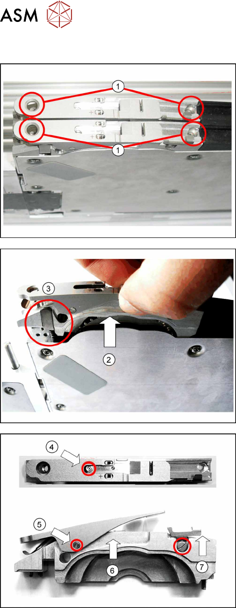
8.5.1 Removing the pickup window
► Remove the 2 marked screws fastening the rel-
evant pickup window and tape duct to the feeder
module. (1)
► Lift the pickup window up and off, together with
the tape duct. (2)
► Also remove the pressure spring and the pres-
sure bracket, to prevent these being lost.(3)
► Remove the fitting screw(4), which is in the tape
duct and which fixes the pickup window axis.
► Loosen the axis on the pickup window(5) and
push this out of the tape duct.
► Lift the pickup window up and off.(6)
► Loosen the collar screw(7) on the rocker lever
and remove this.
8 Repairs to SmartFeeder 2x8 mm X
8.5 Pickup window
Service Manual SIPLACE SmartFeeder 4 - 104 mm X 11/2017 141
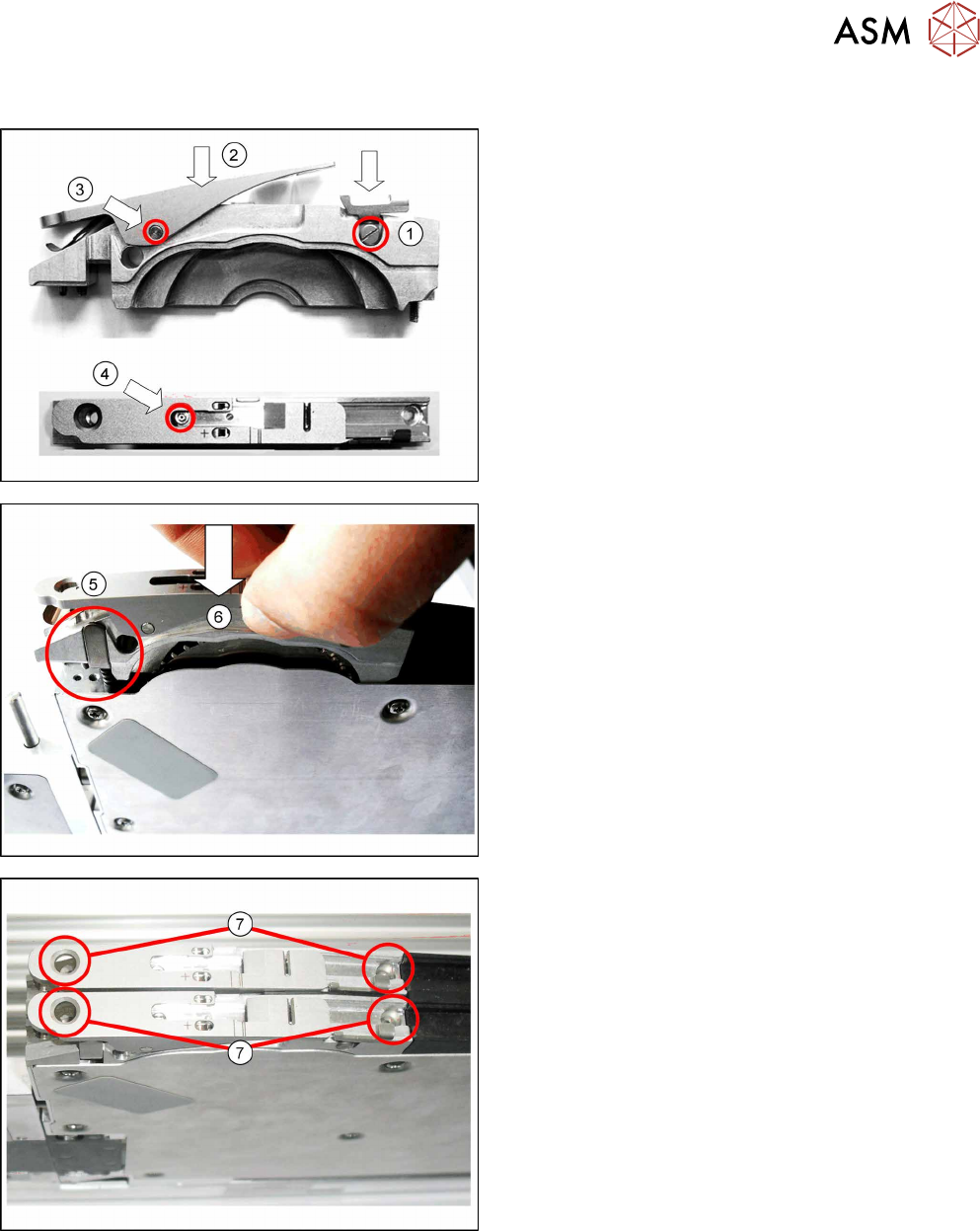
8.5.2 Fitting the pickup window
► Insert the rocker lever and fix it into place with the
marked collar screw.(1)
► Fit the pickup window onto the tape duct from
above.(2)
► Push the axis into the tape duct and fix this into
place.(3)
► Use the fitting screw to fix the pickup window to
the tape duct.(4)
► Insert the pressure spring and then the pressure
bracket on it.(5)
► Insert the pickup window and tape duct as
shown.(6)
► Use the 2 marked screws (with which the pickup
window was previously fastened) to fasten the
pickup window and tape duct.(7)
8 Repairs to SmartFeeder 2x8 mm X
8.6 Splice sensor / dummy
142 Service Manual SIPLACE SmartFeeder 4 - 104 mm X 11/2017
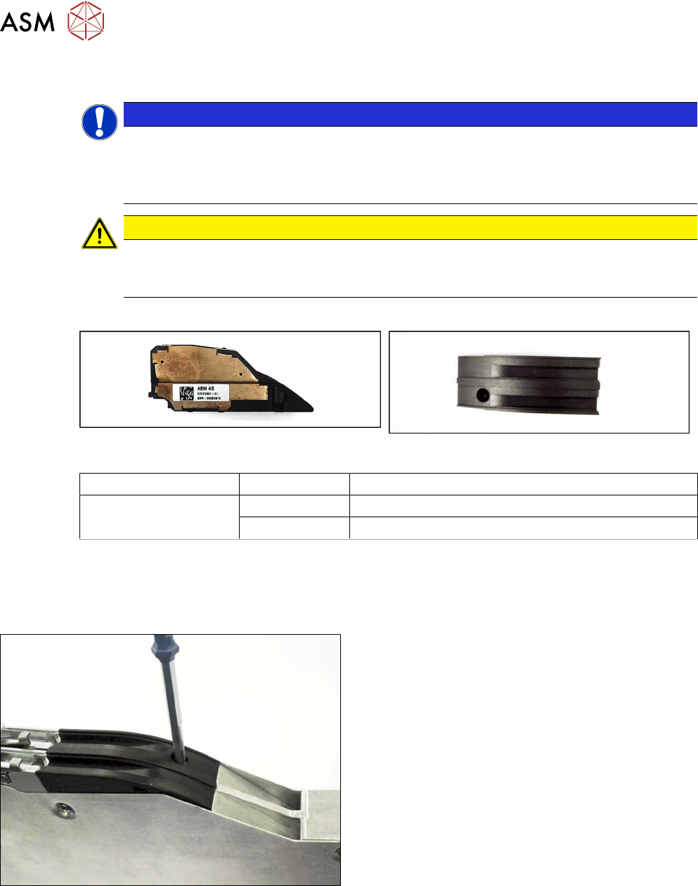
8.6 Splice sensor / dummy
NOTICE
A dummy splice sensor or two splice sensors
The feeder module must always be fitted with either one dummy splice sensor or two splice
sensors.
To fasten the splice sensors, you need 2 screws: the dummy sensor only needs one.
CAUTION
Electrostatic charge
When removing and fitting the splice sensor, observe the currently applicable ESD
guidelines.
Required spare part
Splice sensor X2x8 Dummy splice sensor X2x8
Feeder module Item no. Designation
SmartFeeder 2x8mmX 03072661-xx Splice sensor X2x8
03072924-xx Dummy splice sensor X2x8
Required tools
●
Phillips screwdriver
8.6.1 Removing the Dummy Splice Sensor
► Place the feeder module down on a stable sur-
face e.g. a single slot EDIF or place the feeder
module on a level and clean surface.
► Loosen the screw fastening the dummy sensor.
Use a Phillips screwdriver for this.