00198505-01_SM_SIPLACE_SmartFeeder_EN.pdf - 第149页
8 Repairs to SmartFeeder 2x8 mm X 8.6 Splice sensor / dummy Service Manual SIPLACE SmartFeeder 4 - 104 mm X 11/2017 149 8.6.5.1 Removing the Cable Splice Sensor ► Place the feeder on a stable, level and clean sur- face. …
8 Repairs to SmartFeeder 2x8 mm X
8.6 Splice sensor / dummy
148 Service Manual SIPLACE SmartFeeder 4 - 104 mm X 11/2017
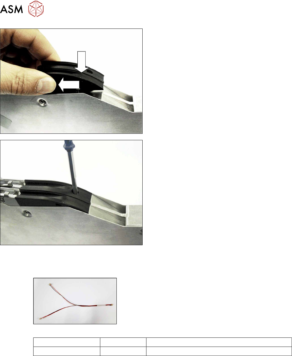
► Lower the dummy sensor completely down.
► Push the dummy sensorforwards, in the direction
of the arrow, as far as the stop.
► Fasten the dummy sensor with a screw (M2,
5x6).
Use a Phillips screwdriver for this.
8.6.5 Cable splice sensor
Required spare parts
Fig.46: Cable splice sensor
Feeder module Item no. Designation
2x8mm X 03063593- xx Cable for splice sensor X2x8
Required tools
●
Phillips screwdriver
●
TORX screwdriver size T8
8 Repairs to SmartFeeder 2x8 mm X
8.6 Splice sensor / dummy
Service Manual SIPLACE SmartFeeder 4 - 104 mm X 11/2017 149
8.6.5.1 Removing the Cable Splice Sensor
► Place the feeder on a stable, level and clean sur-
face.
► Remove the left and right side covers. (See 8.3.1
"Removing the Left Side Cover" [}135], 8.3.3
"Removing the Right Side Cover" [}136])
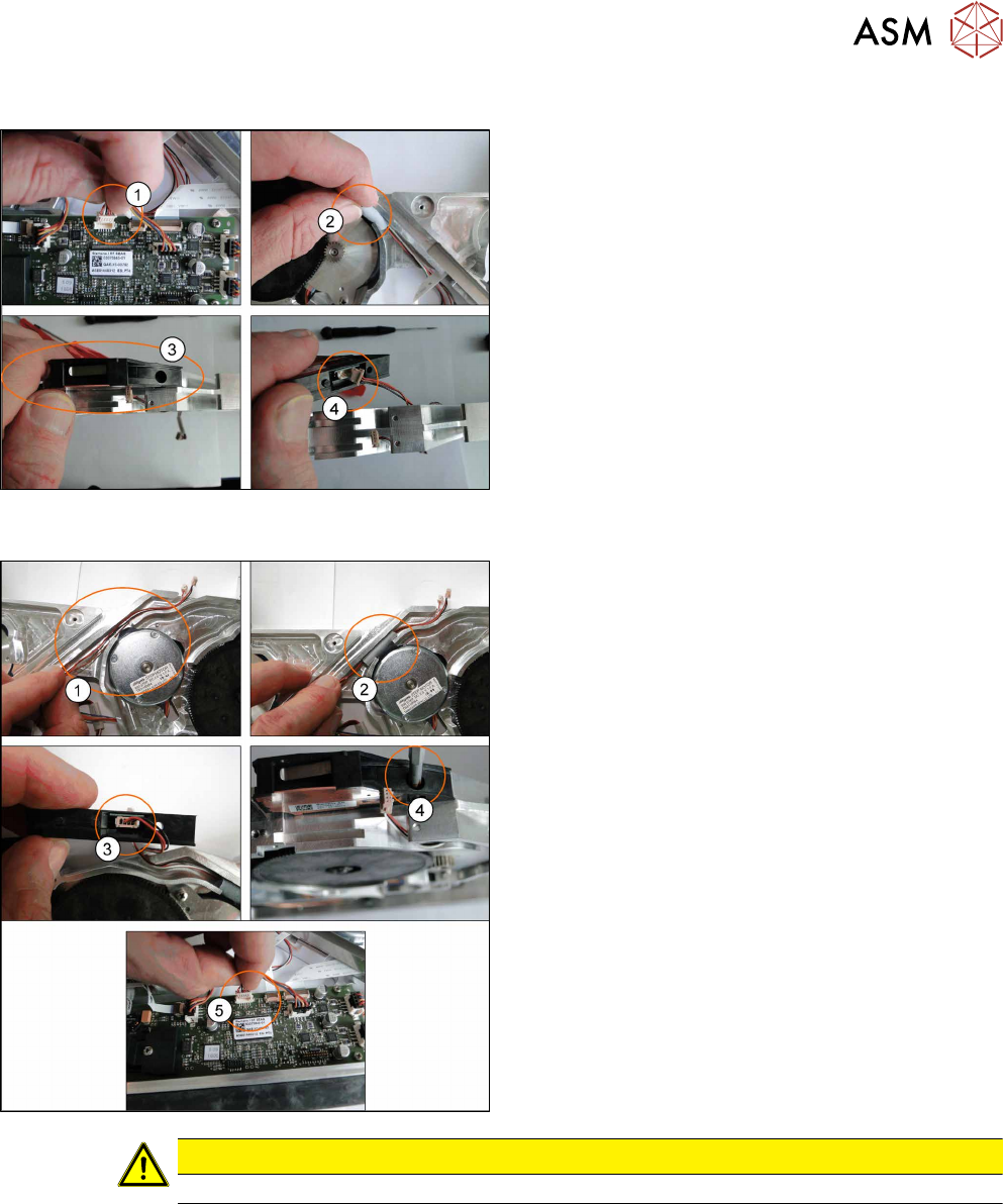
► Disconnect the connector from the main
board(1).
► Remove the seal band left and right(2).
► Remove the M2.5x6 screw from splice sensor(3)
and disconnect the cables(4).
8.6.5.2 Fitting the Cable Splice Sensor
► Lay the new cables(1).
► Place the seal band left and right level with the
channel. Ensure the cables can move freely.(2).
► Reconnect the cables to the splice sensor(3).
► Refit the splice sensor using the M2 5x6
screw(4).
► Connect the connector to the main board(5).
► Fit the left and right side covers. (See 8.3.2 "Fit-
ting the Left Side Cover" [}136], 8.3.4 "Fitting the
Right Side Cover" [}137])
CAUTION
Ensure the cables are not trapped between housing, splice sensor and covers.
8 Repairs to SmartFeeder 2x8 mm X
8.7 Drives
150 Service Manual SIPLACE SmartFeeder 4 - 104 mm X 11/2017
8.7 Drives
8.7.1 Shifted gear for tape drive
NOTICE
Spare parts kit
Due to the potential wear of plastic toothed wheels, it is recommended that, when you find it
necessary to replace one shifted gear or toothed wheel, you also replace the other one.
For this purpose, we recommend the spare parts kit "ETP gear set tape X
2x8mm“ [03095484-xx], which contains both toothed wheels with washers and circlips.
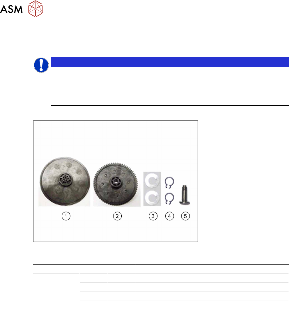
Required spare parts
Fig.47: Spare parts kit "ETP gear set tape X 2x8mm" [03095484-xx]
The spare parts provided in the gear set are listed in the following table:
Feeder module Position Number Item no. Designation
SmartFeeder
2x8mmX
1 03095484-xx ETP drive unit tape X 2x8mm
1 1 03070908-xx Shifted gear 1 tape PA /X2x8
2 1 03070911-xx Toothed wheel 4 tape PA /X2x8
3 2 03083028-xx DIN 988-3x6x0.1-1.4310 (washer)
4 2 00305726-xx DIN 471-3x0.4-C67 (circlip)
5 1 03079902-xx Threaded axis toothed wheel 4 tape / X2x8
In the SmartFeeder 2x8mmX, the toothed wheels for the shifted gear tape drive are fitted in differ-
ent ways.
The drive for the left lane is fitted with the "toothed wheel 4 tape PA /X2x8“ [03070911-xx] with the
"threaded axis toothed wheel 4 tape / X2x8" [03079902-xx]. The "shifted gear 1 tape PA /
X2x8" [03070908-xx], and the "toothed wheel 4 tape PA /X2x8" for the right lane are fitted with
washer and circlip.
The spare parts kit "ETP gear set tape X 2x8mm" [03095484-xx] contains all the parts in the follow-
ing table, in the quantities listed.
Required tools
●
Circlip pliers for outer rings 3-10 mm
●
Allen key 0.35Nm
●
Tweezers