00198505-01_SM_SIPLACE_SmartFeeder_EN.pdf - 第178页
8 Repairs to SmartFeeder 2x8 mm X 8.15 Handle assembly with control panel 178 Service Manual SIPLACE SmartFeeder 4 - 104 mm X 11/2017 ► Carefully place the feeder module on its right side. ► Open the bar on the flat ribb…
8 Repairs to SmartFeeder 2x8 mm X
8.15 Handle assembly with control panel
Service Manual SIPLACE SmartFeeder 4 - 104 mm X 11/2017 177
8.15 Handle assembly with control panel
NOTICE
You must replace the whole assembly
The individual assemblies (e.g. board or cover foil) are attached to the base unit of the
handle with adhesive and cannot be replaced individually. The handle must be replaced as
a complete unit.
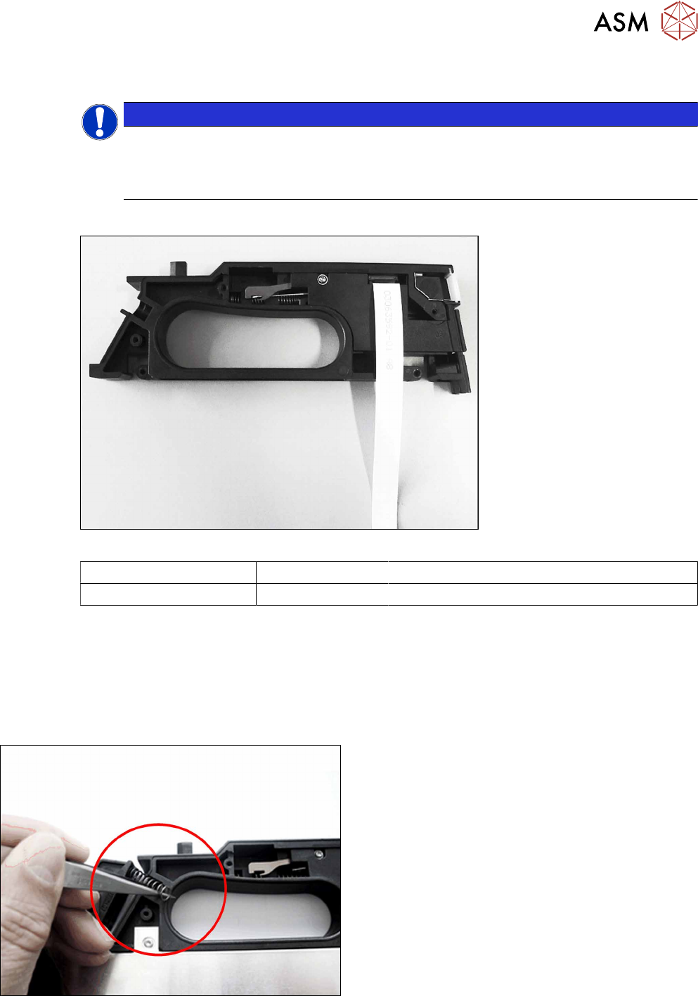
Required spare part
Fig.62: Handle assembly
Feeder module Item no. Designation
SmartFeeder 2x8mmX 03072432Sxx Handle X2x8 (prefitted with flat ribbon cable)
Required tools
●
Phillips screwdriver 0.6Nm
●
TORX screwdriver size T8, 0.6Nm
●
Tweezers
8.15.1 Removing the handle assembly
► Remove the left and right side cover (see 8.3.1
"Removing the Left Side Cover" [}135] and 8.3.3
"Removing the Right Side Cover" [}136]).
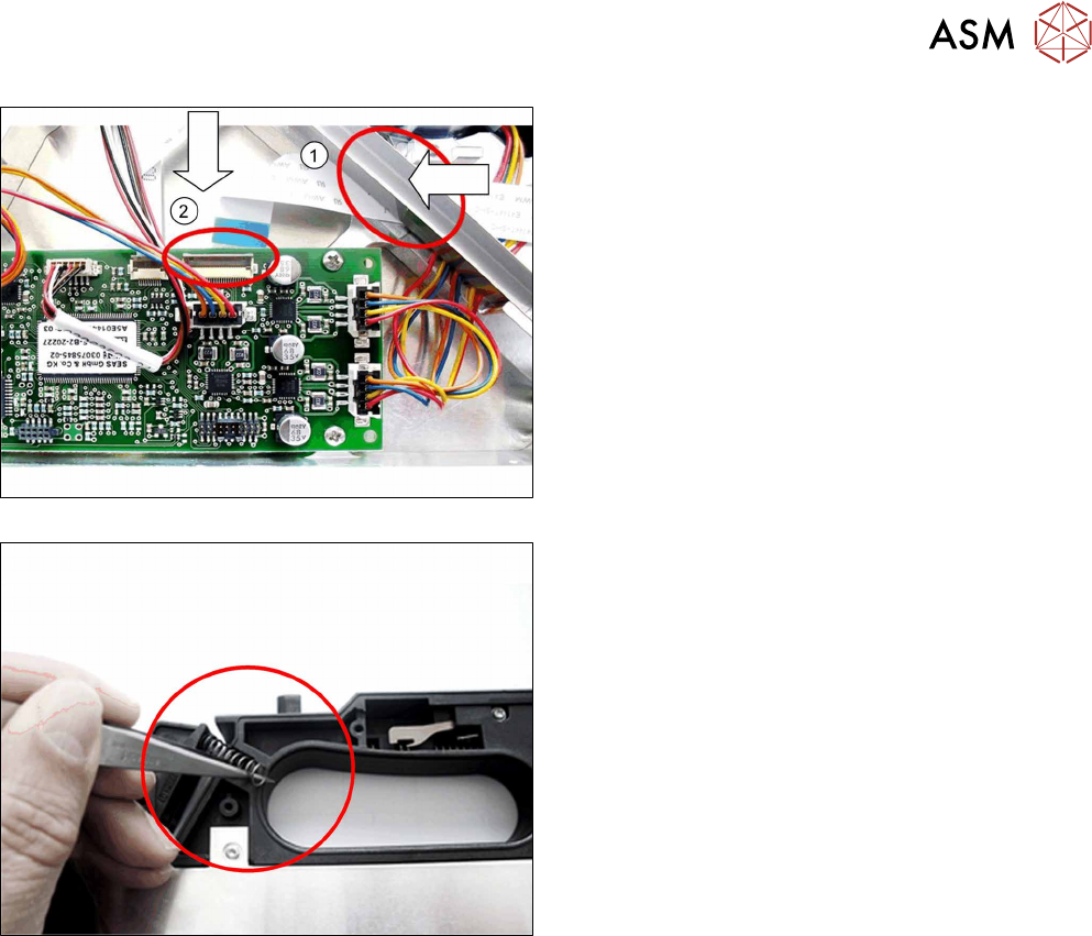
► Remove the two pressure springs from the rock-
ers.
8 Repairs to SmartFeeder 2x8 mm X
8.15 Handle assembly with control panel
178 Service Manual SIPLACE SmartFeeder 4 - 104 mm X 11/2017
► Carefully place the feeder module on its right
side.
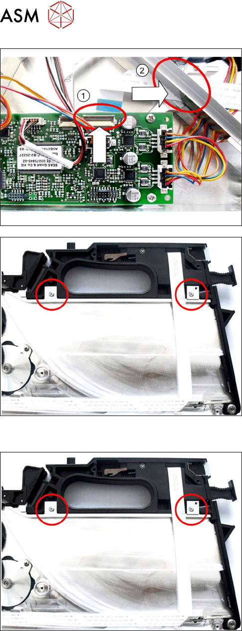
► Open the bar on the flat ribbon connection on the
control board.(1)
► Unplug the flat ribbon cable form the connection.
► Carefully pull the flat ribbon cable completely out
through the feedthrough on the tape duct. (2)
► Carefully pull the flat ribbon cable off the adhes-
ive points.
► Remove the two screws marked in the diagram,
which are fastening the handle.
► Stand the feeder module up.
► Open the foil disposal flap.
► Push the handle up to the right-hand side and out
of the feeder module frame.
► Close the foil container flap.
8.15.2 Fitting the handle assembly
► Stand the feeder module up.
► Open the foil disposal flap.
► Push the handle from the right-hand side, as far
as the stop in the feeder module frame.
► Close the foil container flap.
► Place the feeder module carefully down on its
right side.
► Fasten the handle using the two marked (see dia-
gram) screws with 0.6Nm.
8 Repairs to SmartFeeder 2x8 mm X
8.16 Control board
Service Manual SIPLACE SmartFeeder 4 - 104 mm X 11/2017 179
► Fold the flat ribbon cable in exactly the same way
as the old cable.
► Run the cable and press it into the cable duct and
onto the double-sided adhesive tape. Replace
the adhesive tape if required.
► Carefully insert the flat ribbon cable completely
through the feedthrough on the tape duct.(1)
When running the cable, make sure that the blue
side points upwards at the end of the cable.
► Insert the end of the flat ribbon cable (with the
blue side pointing upwards) as far as the stop in
the marked flat ribbon connection on the control
board. (2)
► Close the connection and make sure that the
cable is firmly fitted.
► Fit the two pressure springs into the rockers.
► Fasten the left and the right side covers (see .
(see 8.3.2 "Fitting the Left Side Cover" [}136]
and 8.3.4 "Fitting the Right Side Cover" [}137]).
8.16 Control board
The control board for the SmartFeeder 2x8mmX is not available as a spare part, because the cali-
bration data for the pickup position are saved in the EEPROM of this board.
A new calibration of the pickup position is therefore only possible at the final inspection point of the
feeder module production at ASM.