00198505-01_SM_SIPLACE_SmartFeeder_EN.pdf - 第184页
9 Repairs to SmartFeeder 12 mm X / 16 mm X 9.3 Side Covers 184 Service Manual SIPLACE SmartFeeder 4 - 104 mm X 11/2017 9.3.1 Removing the Left Side Cover ► Carefully place the feeder module with the right- side side down…
9 Repairs to SmartFeeder 12 mm X / 16 mm X
9.3 Side Covers
Service Manual SIPLACE SmartFeeder 4 - 104 mm X 11/2017 183
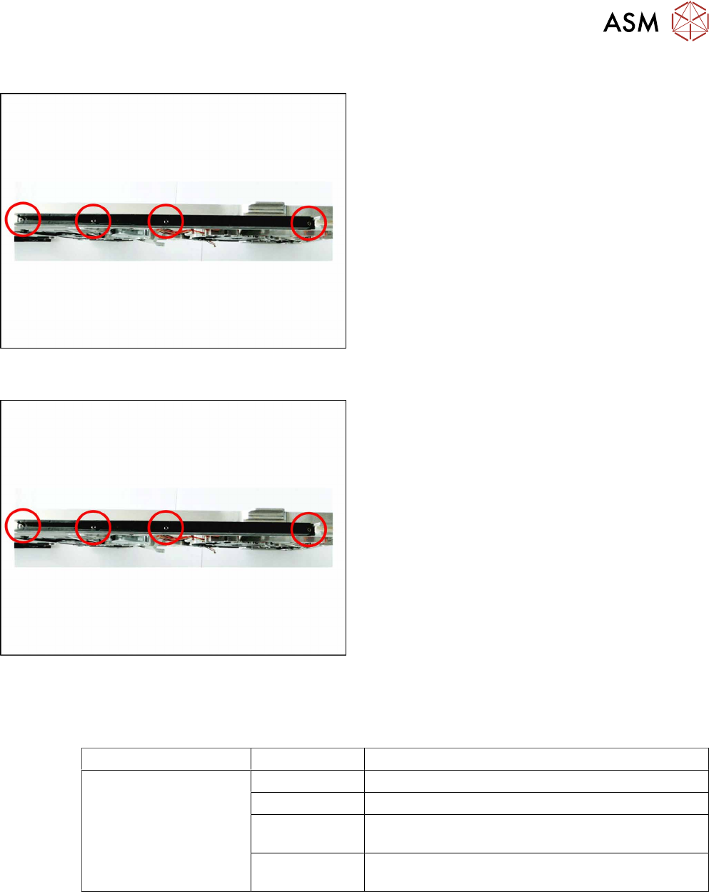
9.2.1 Removing the Sliding Guide
► Turn the feeder module so that its underside is at
the top.
► Remove the 4 marked screws on the sliding
guide.
► Lift the sliding guide upwards and off.
9.2.2 Fitting the Sliding Guide
► Turn the feeder module so that its underside is at
the top.
► Fit the slide bearing – as illustrated – to the un-
derside of the feeder module.
Observe the arrangement of the drilled holes in
the slide bearing.
► Push the slide bearing, as shown, forward to-
wards the front slide bearing, as far as the stop.
► Now lower the two snap tabs of the slide bearing
into the openings provided on the underside of
the feeder module.
► Use the 4 screws to fix the slide bearing with
0.6Nm to the feeder module.
9.3 Side Covers
Required spare part
Feeder module Item no. Designation
SmartFeeder 12mm X
SmartFeeder 16mm X
03083858Sxx Cover plate left X12/X16 V2
03083836Sxx Cover plate right X12/X16 V2
03010209-xx ISO 7045 - M2.5 x 6-A2-50-H
(Phillips screws)
03033796-xx RF-SN75-2.5 x 6-9.8
(TORX screws)
Required tools
●
Phillips screwdriver 0.6Nm
●
TORX screwdriver 0.6Nm, size T8
9 Repairs to SmartFeeder 12 mm X / 16 mm X
9.3 Side Covers
184 Service Manual SIPLACE SmartFeeder 4 - 104 mm X 11/2017
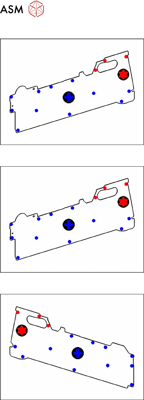
9.3.1 Removing the Left Side Cover
► Carefully place the feeder module with the right-
side side down on a stable, level and clean sur-
face.
► Loosen the screws as shown in the diagram.
The 3 red dots point to the screws for which you need
a TORX screwdriver with a torque of 0.6Nm.
The blue dots point to the screws for which you need a
Phillips screwdriver with a torque of 0.6Nm.
9.3.2 Fitting the Left Side Cover
► Carefully place the feeder module with the right-
side side down on a stable, level and clean sur-
face.
► Fix the screws as shown in the diagram. Begin
with the inner screws and work towards the out-
side.
The 3 red dots point to the screws for which you need
a TORX screwdriver with a torque of 0.6Nm.
The blue dots point to the screws for which you need a
Phillips screwdriver with a torque of 0.6Nm.
9.3.3 Removing the Right Side Cover
► Carefully place the feeder module with the left-
hand side down on a stable, level and clean sur-
face.
► Loosen the screws as shown in the diagram.
The 3 red dots point to the screws for which you need
a TORX screwdriver with a torque of 0.6Nm.
The blue dots point to the screws for which you need a
Phillips screwdriver with a torque of 0.6Nm.
9 Repairs to SmartFeeder 12 mm X / 16 mm X
9.4 EDIF
Service Manual SIPLACE SmartFeeder 4 - 104 mm X 11/2017 185
9.3.4 Fitting the Right Side Cover
► Carefully place the feeder module with the left-
hand side down on a stable, level and clean sur-
face.
► Fix the screws as shown in the diagram. Begin
with the inner screws and work towards the out-
side.
The 3 red dots point to the screws for which you need
a TORX screwdriver with a torque of 0.6Nm.
The blue dots point to the screws for which you need a
Phillips screwdriver with a torque of 0.6Nm.
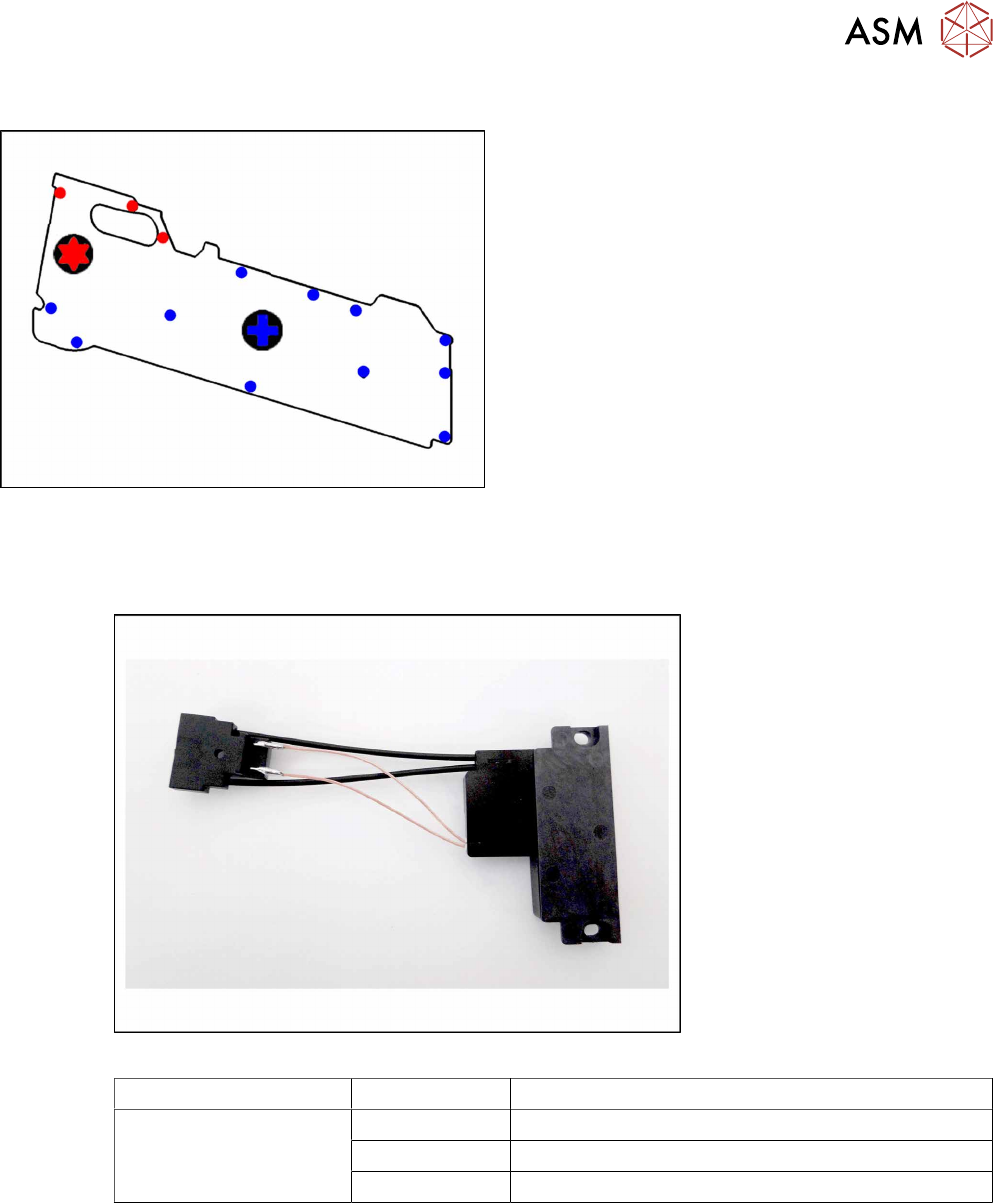
9.4 EDIF
Required spare part
Fig.65: EDIF secondary assembly
Feeder module Item no. Designation
SmartFeeder 12mm X
SmartFeeder 16mm X
03125222-xx EDIF secondary assembly X Smart
03012683-xx Pressure spring D-027
03068667-xx Collar screw ø4x4.5 M3 /X2x8
Required tools
●
Flat-bladed screwdriver 0.6Nm
●
Phillips screwdriver 0.6Nm
●
Phillips screwdriver 0.2Nm
●
TORX screwdriver 0.6Nm, size T8