00198505-01_SM_SIPLACE_SmartFeeder_EN.pdf - 第190页
9 Repairs to SmartFeeder 12 mm X / 16 mm X 9.5 Pickup window 190 Service Manual SIPLACE SmartFeeder 4 - 104 mm X 11/2017 ► Lift the pickup window up and off the tape duct. 9.5.2 Fitting the Pickup Window ► Fit the pickup…
9 Repairs to SmartFeeder 12 mm X / 16 mm X
9.5 Pickup window
Service Manual SIPLACE SmartFeeder 4 - 104 mm X 11/2017 189
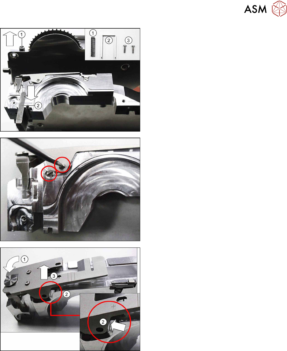
► Remove the compression spring(1), the pressure
fork(2) and the two screws(3), so that these are
not lost.
► Place the feeder module carefully down on a
stable, level and clean surface.
► Place the tape duct carefully down on its right
side, onto a stable, level and clean surface.
► Remove the two marked screwed axes.
► Press the front of the pickup window down as far
as the stop.(1)
Make sure that the pickup window is pressed into
the recess on the tape duct.(2)
► Press the pickup window into the recess on the
tape duct.(3)
Make sure that the pickup window is pushed out
of the snap tab on the right side of the tape duct.
9 Repairs to SmartFeeder 12 mm X / 16 mm X
9.5 Pickup window
190 Service Manual SIPLACE SmartFeeder 4 - 104 mm X 11/2017
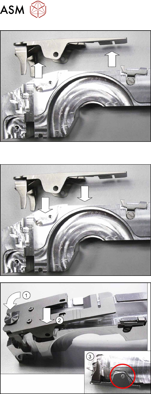
► Lift the pickup window up and off the tape duct.
9.5.2 Fitting the Pickup Window
► Fit the pickup window onto the tape duct from
above.
► Press the front of the pickup window down.(1)
► Push the pickup window sideways into the posi-
tion shown.(2)
Make sure that the pickup window engages in the
snap tab on the right-hand side of the tape
duct.(3)
9 Repairs to SmartFeeder 12 mm X / 16 mm X
9.5 Pickup window
Service Manual SIPLACE SmartFeeder 4 - 104 mm X 11/2017 191
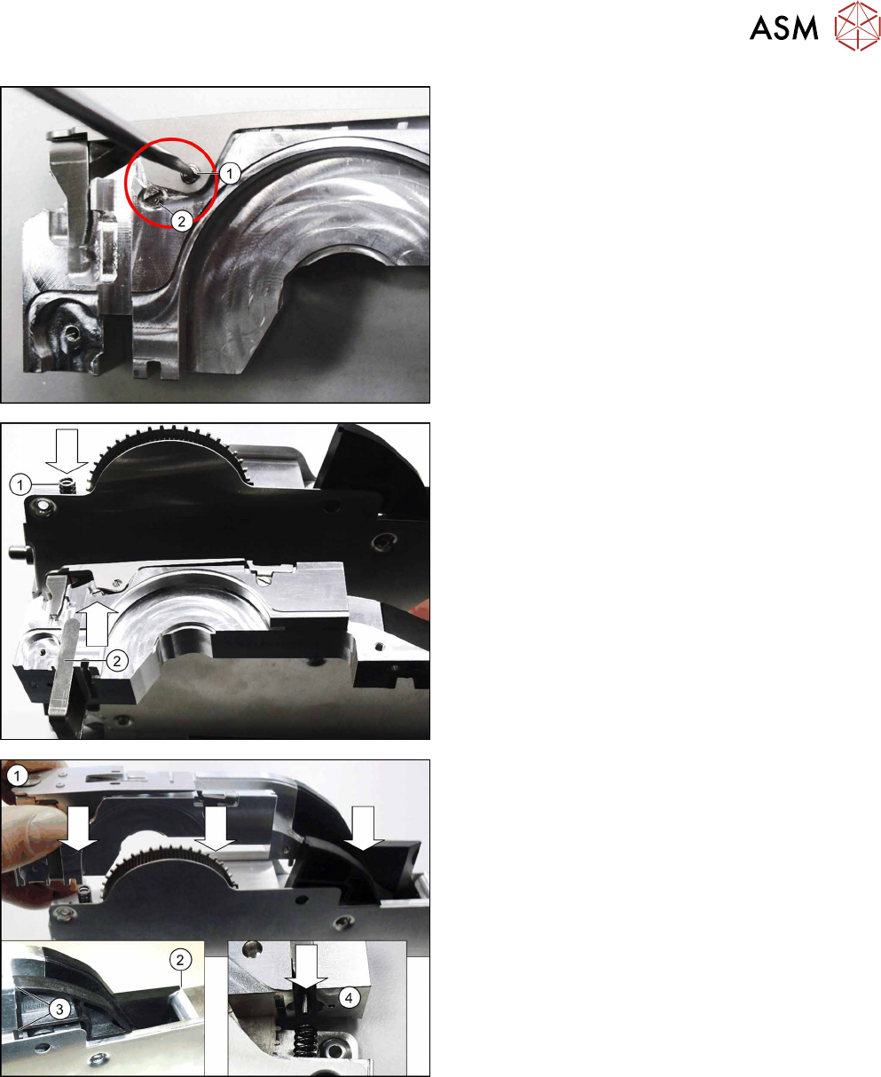
► Fix the pickup window into place using a screwed
axle and 0.35Nm. (1)
Make sure that the head of the screwed axle is
flush with the side of the pickup window.
► Fasten the second screwed axle with 0.35Nm.
(2)
► Fit the compression springs into the feeder mod-
ule base unit as shown in the diagram. (1)
► Push the pressure fork from below against the
tape duct.(2)
► Fit the tape duct from above onto the feeder
module.(1)
Take care when doing this that, at the back, the
tape duct is flush with the ramp(2) and the splice
sensor (3). At the front, the pin in the pressure
fork must engage in the compression spring.(4)