00198505-01_SM_SIPLACE_SmartFeeder_EN.pdf - 第192页
9 Repairs to SmartFeeder 12 mm X / 16 mm X 9.5 Pickup window 192 Service Manual SIPLACE SmartFeeder 4 - 104 mm X 11/2017 ► Stand the feeder module up. ► Hold the pickup window and tape duct with one hand (as shown) to co…
9 Repairs to SmartFeeder 12 mm X / 16 mm X
9.5 Pickup window
Service Manual SIPLACE SmartFeeder 4 - 104 mm X 11/2017 191
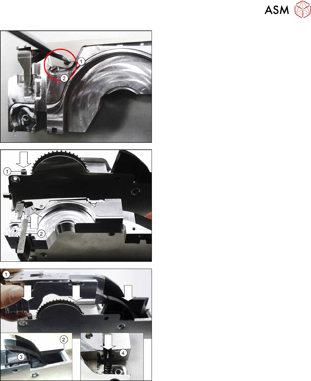
► Fix the pickup window into place using a screwed
axle and 0.35Nm. (1)
Make sure that the head of the screwed axle is
flush with the side of the pickup window.
► Fasten the second screwed axle with 0.35Nm.
(2)
► Fit the compression springs into the feeder mod-
ule base unit as shown in the diagram. (1)
► Push the pressure fork from below against the
tape duct.(2)
► Fit the tape duct from above onto the feeder
module.(1)
Take care when doing this that, at the back, the
tape duct is flush with the ramp(2) and the splice
sensor (3). At the front, the pin in the pressure
fork must engage in the compression spring.(4)
9 Repairs to SmartFeeder 12 mm X / 16 mm X
9.5 Pickup window
192 Service Manual SIPLACE SmartFeeder 4 - 104 mm X 11/2017
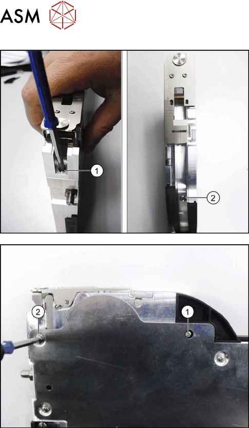
► Stand the feeder module up.
► Hold the pickup window and tape duct with one
hand (as shown) to counteract the spring force of
the compression spring.
► Fasten the front screw of the tape duct with
0.6Nm(1).
► Fasten the back screw with 0.6Nm to the tape
duct.(2)
► Carefully place the feeder module with the right
side down on a stable, level and clean surface.
► Fasten the screw with 0.6Nm to the splice
sensor.(1)
► Fasten the top left screw with 0.6Nm to the side
cover(1).
9 Repairs to SmartFeeder 12 mm X / 16 mm X
9.6 Splice Sensor
Service Manual SIPLACE SmartFeeder 4 - 104 mm X 11/2017 193
9.6 Splice Sensor
NOTICE
Splice sensor or dummy
The feeder module can be fitted with either a splice sensor or a dummy splice sensor. The
procedure is the same in both cases.
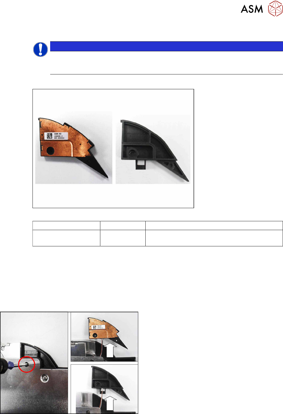
Required spare part
Fig.67: Splice sensor (left) / Splice sensor dummy (right)
Feeder module Item no. Designation
SmartFeeder 12mm X
SmartFeeder 16mm X
03085638- xx
03085517Sxx
Splice sensor X12/X16 V2
Dummy splice sensor X12/X16 V2
Required tools
●
Flat-bladed screwdriver size 1
●
Phillips screwdriver 0.6Nm
●
TORX screwdriver 0.6Nm, size T8
●
Tweezers
9.6.1 Removing the Splice Sensor (Dummy)
► Carefully place the feeder module with the right-
side side down on a stable, level and clean sur-
face.
► Remove the screw shown in the diagram.
► Remove the splice sensor or splice sensor
dummy and carefully pull out the cable a little.