00198505-01_SM_SIPLACE_SmartFeeder_EN.pdf - 第199页
9 Repairs to SmartFeeder 12 mm X / 16 mm X 9.7 Drives and gears Service Manual SIPLACE SmartFeeder 4 - 104 mm X 11/2017 199 9.7 Drives and gears 9.7.1 Shifted gear for tape drive Required spare parts Fig.69: ETP gear se…
9 Repairs to SmartFeeder 12 mm X / 16 mm X
9.6 Splice Sensor
198 Service Manual SIPLACE SmartFeeder 4 - 104 mm X 11/2017
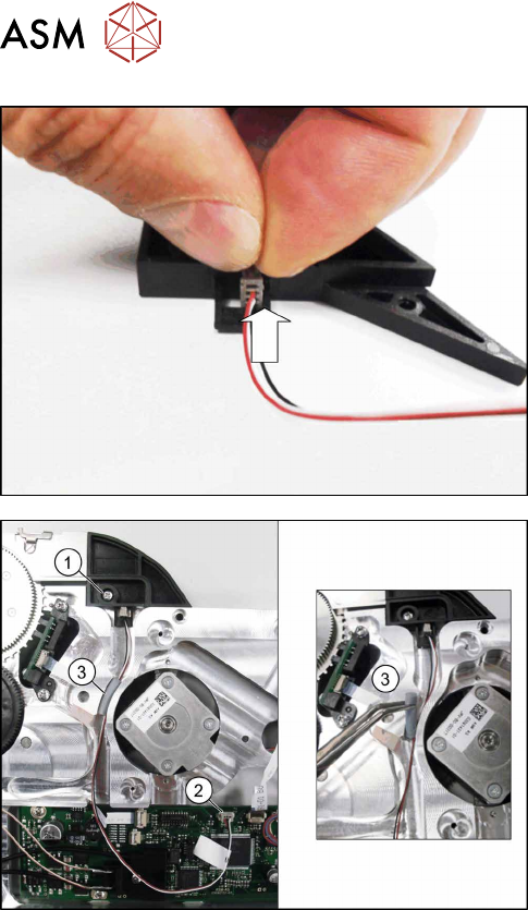
For the splice sensor dummy:
► Insert the 4-pin connector for the splice sensor
cable into the splice sensor dummy, as shown in
the diagram.
► Fix the splice sensor (dummy) using the marked
screw and 0.6 Nm. (1).
► Plug the 3-pin connector for the splice sensor
cable into the connection on the control
board.(2)
► Run the cable in the cable duct as shown in the
diagram.
► Fix the cable with the cover cord (rubber) in the
cable duct.(3)
We advise that you use a pair of tweezers for
this.
► Fasten the left side cover (see 9.3.2 "Fitting the
Left Side Cover" [}184].
9 Repairs to SmartFeeder 12 mm X / 16 mm X
9.7 Drives and gears
Service Manual SIPLACE SmartFeeder 4 - 104 mm X 11/2017 199
9.7 Drives and gears
9.7.1 Shifted gear for tape drive
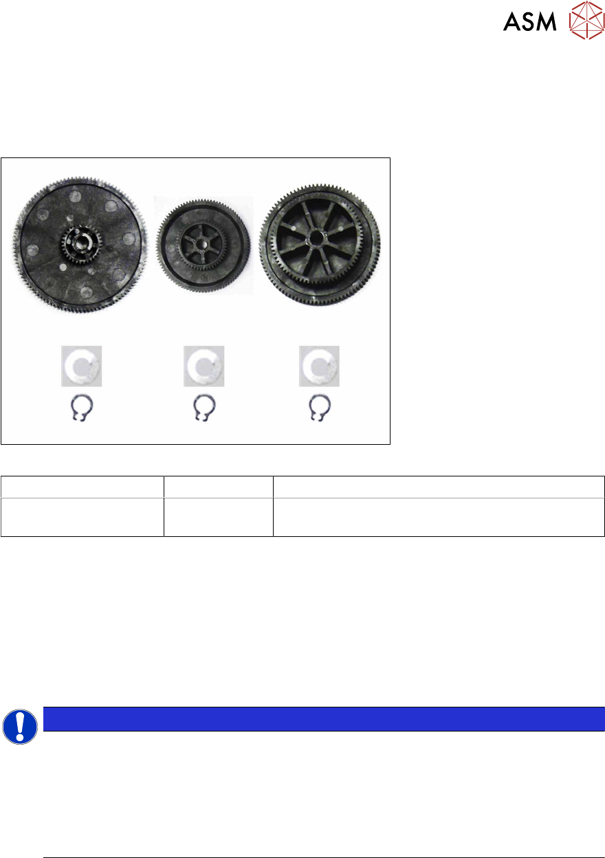
Required spare parts
Fig.69: ETP gear set tape X12/16
Feeder module Item no. Designation
SmartFeeder 12mm X
SmartFeeder 16mm X
03095425- xx ETP gear set tape X12/16
Tools and equipment required
●
Phillips screwdriver 0.6Nm
●
TORX screwdriver 0.6Nm, size T8
●
Circlip pliers for outer rings 3-10 mm
●
Tweezers
●
Polylub GLY 801 (grease)
●
Ethanol
NOTICE
Avoiding gear damage
If your feeder module has a bronze shifted gear, this will need to be completely replaced
with a plastic shifted gear.
The use of bronze and plastic shifted gears at the same time is not permitted and can
cause damage to the gear unit.
Shifted gears may not be replaced one at a time. Always replace the complete shifted gear
assembly.
9 Repairs to SmartFeeder 12 mm X / 16 mm X
9.7 Drives and gears
200 Service Manual SIPLACE SmartFeeder 4 - 104 mm X 11/2017
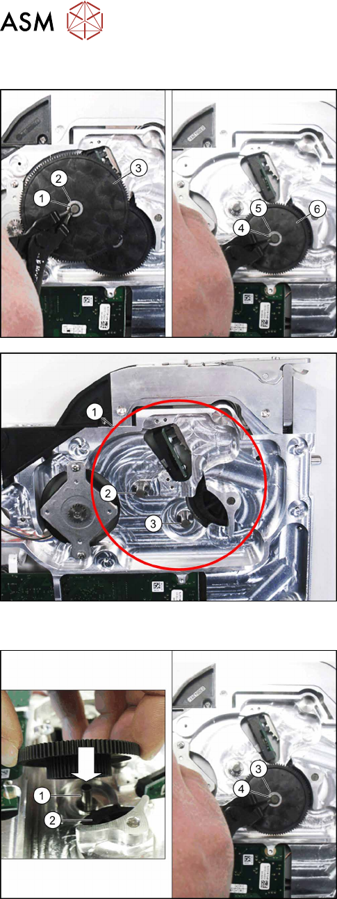
9.7.1.1 Removing Gear Stages 1 and 2
► Remove the right side cover (see 9.3.3 "Remov-
ing the Right Side Cover" [}184])
► Remove the circlip(1) on gear stage1.
► Remove the washer (2) on gear stage1
► Remove gear stage1.(3)
► Remove the circlip(4) on gear stage2.
► Remove the washer (5) on gear stage2
► Remove gear stage 2.(6)
► Clean the marked parts of the gear stage housing
(1) with a lint-free cloth and remove the grease
from the gear axes with a little ethanol.
► Slightly grease the gear axes (2,3) with Poly-
lubGLY801.
9.7.1.2 Fitting Gear Stages 1 and 2
► Fit gear stage2 with the smaller toothed wheel
down onto the marked axle. (1)
Make sure that the smaller toothed wheel en-
gages down in gear stage3(2).
► Fit the washer into place.(3)
► Secure gear stage 2 with a new circlip. (4)