00198505-01_SM_SIPLACE_SmartFeeder_EN.pdf - 第234页
10 Repairs to SmartFeeder 24 - 104 mm X 10.4 EDIF 234 Service Manual SIPLACE SmartFeeder 4 - 104 mm X 11/2017 10.4 EDIF Required spare part Fig.85: EDIF secondary assembly X Smart Feeder module Item no. Designation Smar…
10 Repairs to SmartFeeder 24 - 104 mm X
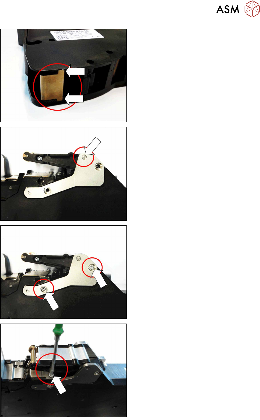
10.3 Side covers
Service Manual SIPLACE SmartFeeder 4 - 104 mm X 11/2017 233
► During assembly of the side wall, make
sure that the two nibs on the leaf spring
are outside the base unit and that the leaf
spring can swing downwards without ob-
struction.
► Carefully place the feeder module with the
right side down on a stable, level and
clean surface.
► Position the sheet metal rocker as shown
on the foil rocker.
Make sure that the threaded axis for the
foil rocker is fed through the metal sheet
as marked.
► Fasten the metal sheet with the two
screws marked in the diagram.
Use a size T8 TORX screwdriver with 0.6
Nm for this.
► Fasten the screw shown in the dia-
gramunder the foil rocker.
Use a size T8 TORX screwdriver with 0.6
Nm for this.
10 Repairs to SmartFeeder 24 - 104 mm X
10.4 EDIF
234 Service Manual SIPLACE SmartFeeder 4 - 104 mm X 11/2017
10.4 EDIF
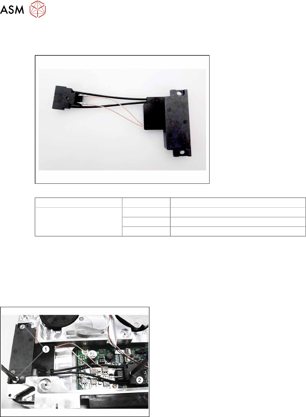
Required spare part
Fig.85: EDIF secondary assembly X Smart
Feeder module Item no. Designation
SmartFeeder 24 – 104 mm X 03125222Sxx EDIF secondary assembly X Smart
03068667-xx Collar screw ø4x4.5 M3 /X2x8
03012683-xx Pressure spring D-027
Required tools
●
Flat-bladed screwdriver 0.6Nm
●
Phillips screwdriver 0.6Nm
●
Phillips screwdriver 0.2Nm
●
TORX screwdriver 0.6Nm, size T8
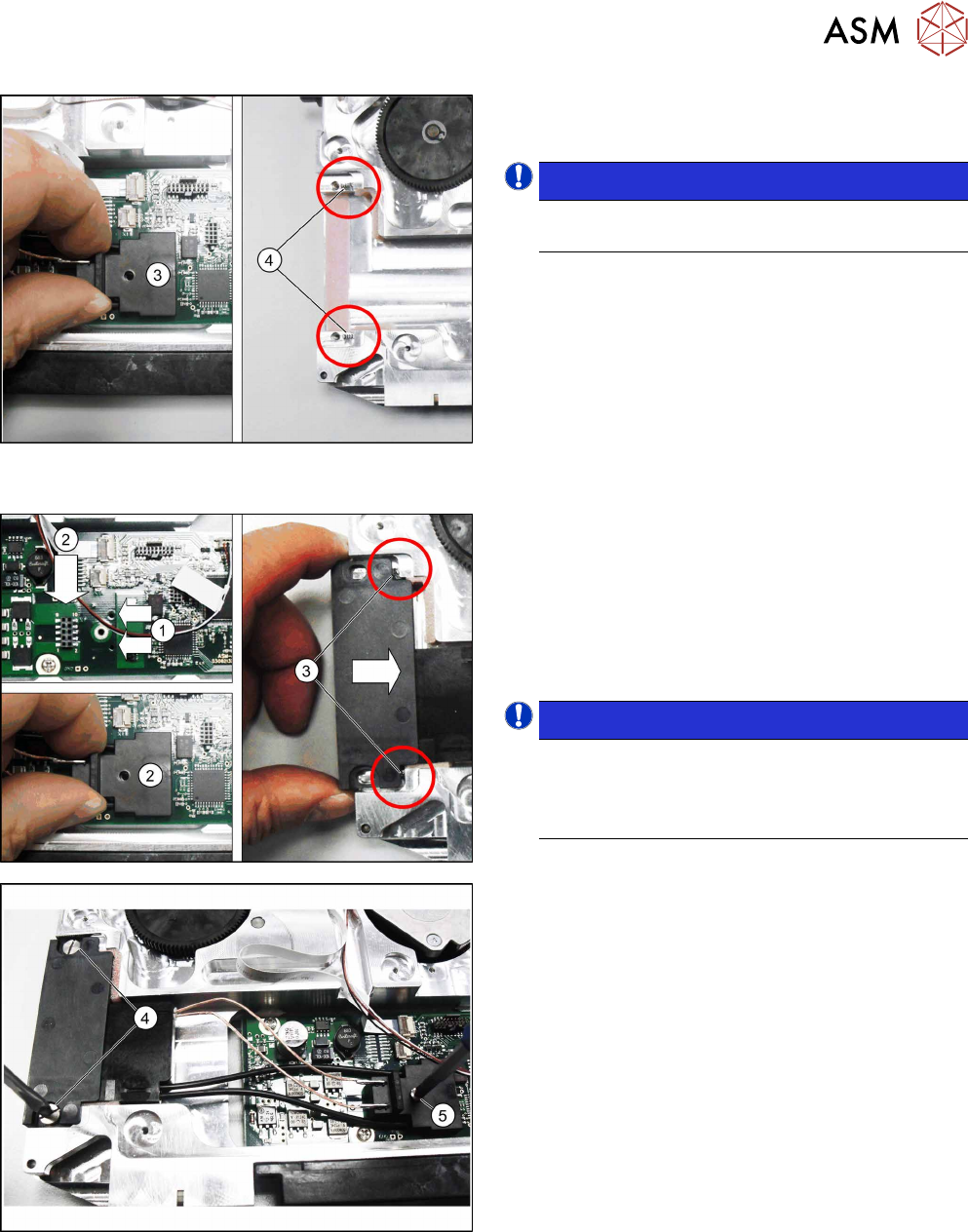
10.4.1 Removing the EDIF
► Remove the left side cover (see 10.3.1 "Remov-
ing/fitting the left side plate" [}230]).
► Loosen the two screws on the EDIF.(1)
► Loosen the screw on the connector.(2)
10 Repairs to SmartFeeder 24 - 104 mm X
10.4 EDIF
Service Manual SIPLACE SmartFeeder 4 - 104 mm X 11/2017 235
► Carefully pull the connector upwards and out.(3)
► Remove the EDIF.
NOTICE!
Make sure that the two springs(4) are not
lost.
.
10.4.2 Fitting the EDIF
► Position the EDIF connector. To do this, insert
the two centering pins on the underside of the
connector in the holes provided on the board.(1)
► Press the EDIF connector onto the marked con-
nection.(2)
► Push the EDIF into the recess at the front of the
feeder module.
NOTICE!
Make sure that the two pressure springs(3)
are behind the EDIF, point straight ahead to
the EDIF and are not distorted when inserted.
Replace any bent pressure springs.
.
► Screw the EDIF into place using the two marked
screws(4) with 0.6Nm.
► Make sure that the EDIF springs back when
slight pressure is applied from the front.
If the EDIF does not spring back, loosen the
screws(4) and make sure that the two springs(3)
are aligned towards the front and are not bent.
► Screw the EDIF connector into place with
0.2Nm.(5)
► Fasten the left side cover (see 10.3.1 "Removing/
fitting the left side plate" [}230]).