00198505-01_SM_SIPLACE_SmartFeeder_EN.pdf - 第254页
10 Repairs to SmartFeeder 24 - 104 mm X 10.7 Drives and gears 254 Service Manual SIPLACE SmartFeeder 4 - 104 mm X 11/2017 10.7.3 Tape drive (hybrid stepping motor) Required spare part Fig.91: Tape drive hybrid stepping …
10 Repairs to SmartFeeder 24 - 104 mm X
10.7 Drives and gears
Service Manual SIPLACE SmartFeeder 4 - 104 mm X 11/2017 253
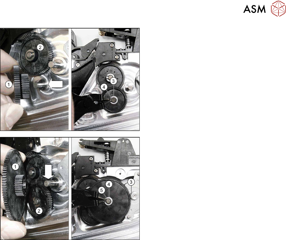
► Fit shifted gear2(1) with the smaller toothed
wheel pointing downwards, onto the axis.
Make sure that the smaller toothed wheel en-
gages down in the other toothed wheel(2).
► Fit the washer into place.(3)
► Secure the shifted gear with a new circlip.(4)
► Fit shifted gear1(1) with the smaller toothed
wheel pointing downwards, onto the axis.(1)
Make sure that the smaller toothed wheel en-
gages down in shifted gear 2 .(2)
The large toothed wheel for the shifted gear en-
gages up in the motor pinion.(3)
► Fit the washer into place.(4)
► Secure the shifted gear with a new circlip.(5)
► Fasten the right side cover (see10.3.2 "Remov-
ing/fitting the right front cover" [}231] ).
10 Repairs to SmartFeeder 24 - 104 mm X
10.7 Drives and gears
254 Service Manual SIPLACE SmartFeeder 4 - 104 mm X 11/2017
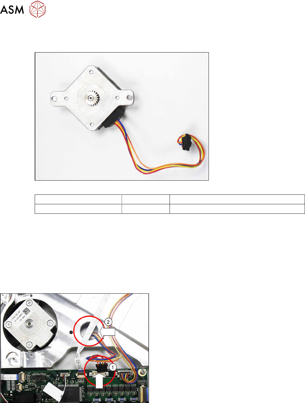
10.7.3 Tape drive (hybrid stepping motor)
Required spare part
Fig.91: Tape drive hybrid stepping motor assembly
Feeder module Item no. Designation
SmartFeeder 24 - 104 mm X 03116587-xx Hybrid stepping motor assembly X24-104Smart
Required tools
●
Phillips screwdriver 0.9Nm
●
TORX screwdriver 0.6Nm, size T8
●
Gauge for tape drive motor X24-104, item no. 03130748-xx
●
Circlip pliers for outer rings 3-10 mm
●
Tweezers
10.7.3.1 Removing the tape drive
► Remove the right side cover (see 10.3.2 "Remov-
ing/fitting the right front cover" [}231])
► Remove the left side plate (see 10.3.1 "Remov-
ing/fitting the left side plate" [}230]).
► Carefully place the feeder module on its right
side.
► Unplug the connector for the tape drive cable
from the connection on the control board.(1)
► Guide the tape drive cable through the marked
opening(2) to the other side of the feeder mod-
ule.
10 Repairs to SmartFeeder 24 - 104 mm X
10.7 Drives and gears
Service Manual SIPLACE SmartFeeder 4 - 104 mm X 11/2017 255
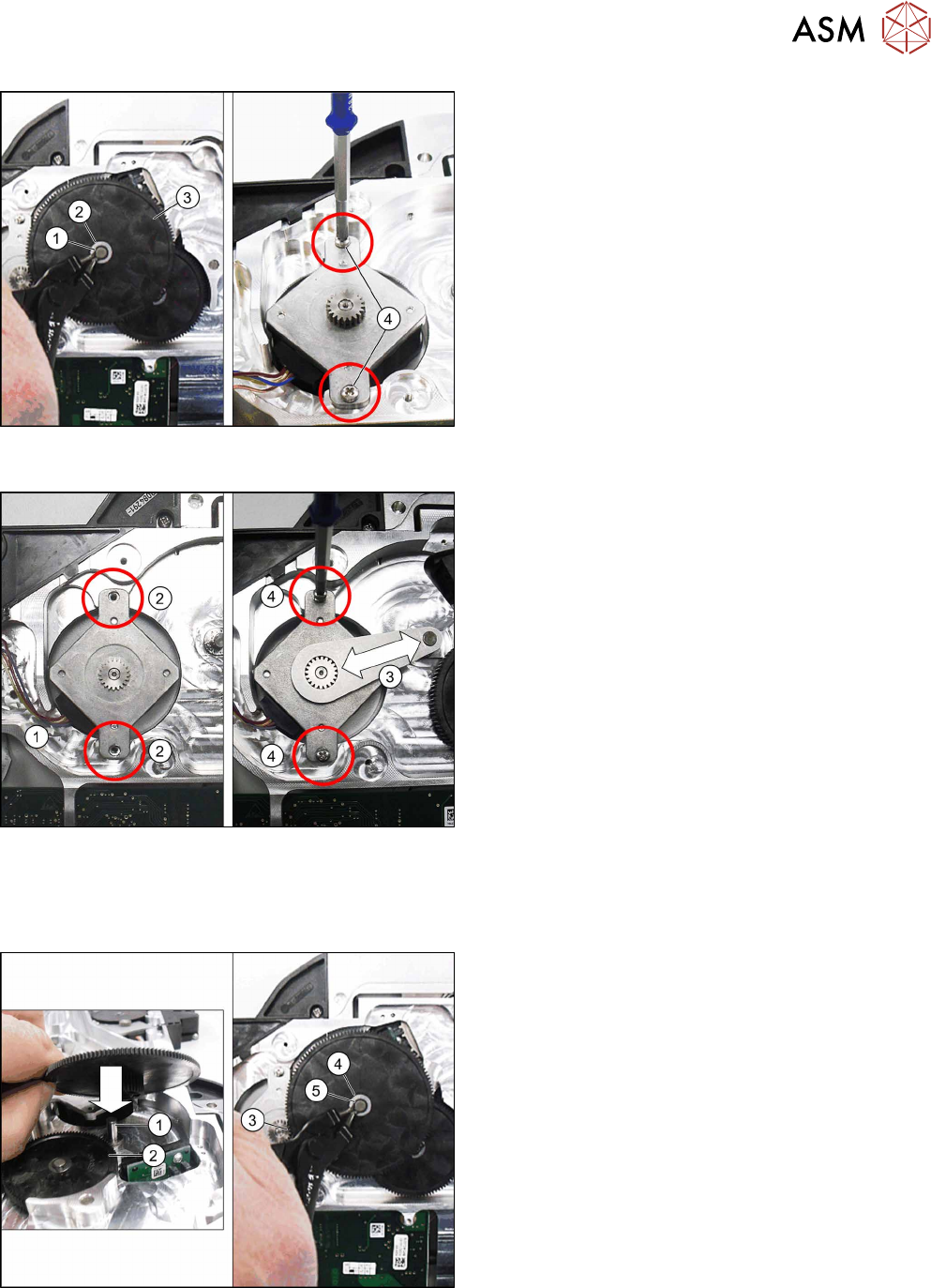
► Carefully place the feeder module down on its left
side.
► Remove the circlip(1) on shifted gear1.
► Remove the washer (2) on shifted gear1
► Remove shifted gear 1.(3)
► Remove the two screws which fasten the tape
drive.(4)
► Remove the tape drive.
10.7.3.2 Fitting the tape drive
► Carefully place the feeder module down on its left
side.
► Insert the tape drive into the recess.
Make sure that the tape drive cable is on the left
side.
► Run the cable in the cable duct.(1)
► Position the tape drive so that you can see the
holes in the feeder module base unit through the
holes in the drive frame.(2)
► Fit the gauge as shown, with the level side point-
ing upwards, onto the pinion of the tape drive and
onto the axis of shifted gear1.(3)
► Position the tape drive so that the pinion and
gauge can not catch in one another.
► Fix the tape drive with the two Phillips screws
ISO 7045 M2.5x8. Use a Phillips screwdriver with
0.9Nm for this.
► Remove the gauge.
► Fit shifted gear1 with the smaller toothed wheel
pointing downwards onto the axis.(1)
Make sure that the smaller toothed wheel en-
gages below with shifted gear2(2).
The large toothed wheel for the shifted gear will
engage above with the tape drive pinion.(3)
► Fit the washer into place.(4)
► Secure shifted gear 1 with a new circlip.(5)