00198505-01_SM_SIPLACE_SmartFeeder_EN.pdf - 第38页
6 Repairs to SmartFeeder 4 mm X 6.5 Pickup window 38 Service Manual SIPLACE SmartFeeder 4 - 104 mm X 11/2017 6.5.1 Removing the Pickup Window ► Carefully place the feeder module with the left side down on a stable, level…
6 Repairs to SmartFeeder 4 mm X
6.5 Pickup window
Service Manual SIPLACE SmartFeeder 4 - 104 mm X 11/2017 37
6.5 Pickup window
Required spare part
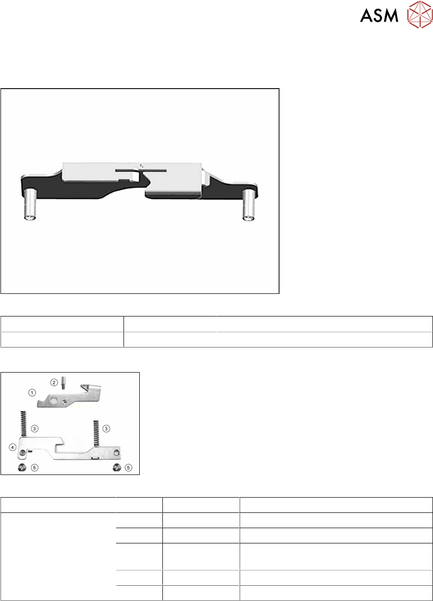
Fig.6: Pickup window assy. X4Smart
Feeder module Item no. Designation
SmartFeeder 4mmX 03153018-01 Pickup window assy. X4Smart V3
Other spare parts
Fig.7: Actuator, pressure springs, counterplate and various screws
Feeder module Position Item no. Designation
SmartFeeder 4mmX 1 03112063Sxx Actuator for pickup window assy. X8Smart
2 00349254Sxx Fitting screw
3 03109568Sxx Pressure spring for pickup window X8S-
mart
4 03080581Sxx Counterplate for pickup window X8Smart
5 03023227-xx ISO 7046-2-M2.5 x 5-A2-70-H
Required tools
●
Phillips screwdriver
6 Repairs to SmartFeeder 4 mm X
6.5 Pickup window
38 Service Manual SIPLACE SmartFeeder 4 - 104 mm X 11/2017
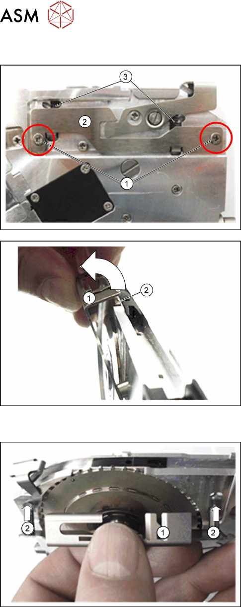
6.5.1 Removing the Pickup Window
► Carefully place the feeder module with the left
side down on a stable, level and clean surface.
► Remove the two Phillips screws (1).
► Make sure that the counterplate(2) does not fall
out.
► Make sure that the pressure springs(3) do not
fall out.
► Move the feeder module to an upright and stable
position.
► Carefully pull the pickup window upwards, over
the pin wheel and away to the left.
6.5.2 Fitting the Pickup Window
► Move the feeder module to an upright and stable
position.
► Guide the pickup window (1) with the two bolts
(2) into the feedthroughs provided for the feeder
module drive.
6 Repairs to SmartFeeder 4 mm X
6.5 Pickup window
Service Manual SIPLACE SmartFeeder 4 - 104 mm X 11/2017 39
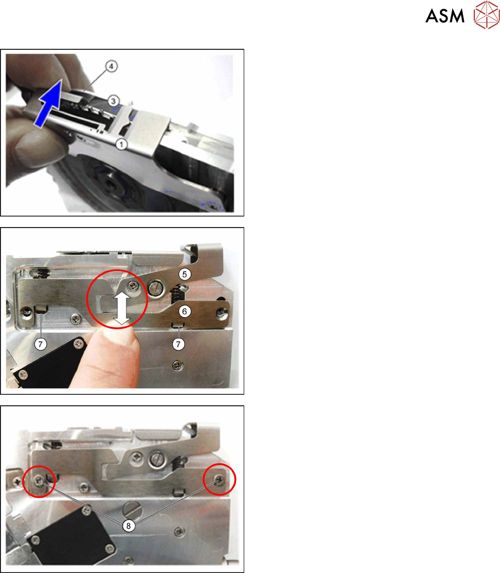
► Carefully guide the pickup window (1) over the
pin wheel (3) and over the right edge (4) of the
feeder module.
► Make sure that, in the marked area, the actu-
ator(5) for the pickup window and the counter-
plate(6) lie flat against the wall of the feeder
module and can be moved up and down.
► Take care when you insert the counterplate that
the springs(7) are completely as shown within
their guidance and that the counterplate can be
inserted neatly.
► Fasten the pickup window (hand-tight) with the
two screws(8) marked in the diagram.
Use a Phillips screwdriver and 0.6Nm.