00198505-01_SM_SIPLACE_SmartFeeder_EN.pdf - 第73页
6 Repairs to SmartFeeder 4 mm X 6.16 Control board Service Manual SIPLACE SmartFeeder 4 - 104 mm X 11/2017 73 ► Carefully life the cap on the foil stuffing unit (5) into the position shown on the feeder module base. Mak…
6 Repairs to SmartFeeder 4 mm X
6.15 Handle with control panel
72 Service Manual SIPLACE SmartFeeder 4 - 104 mm X 11/2017
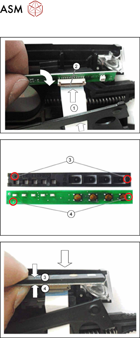
6.15.1.2 Fitting the Control Panel and Board
► If this is not open, swing the bracket on the flat
ribbon connection(2) on the board upwards.
► Push the flat ribbon cable(1) through the foil
stuffing unit cap, as shown, with the blue side
pointing upwards.
► Push the flat ribbon cable(1), with the blue side
pointing upwards, further into the flat ribbon cable
connection(2), on the board.
► Make sure that the flat ribbon cable contacts lie
against the contacts on the connection.
► Swing the bracket on the flat ribbon connection
down(2).
► Insert the control panel(3) with the marked pins
into the marked holes(4) on the board.
► Push the control panel(3) together with the
board(4) sideways into the feeder module guid-
ance provided.
► Make sure that the flat ribbon cable is not
pinched or pulled out of the connection on the
board.
6 Repairs to SmartFeeder 4 mm X
6.16 Control board
Service Manual SIPLACE SmartFeeder 4 - 104 mm X 11/2017 73
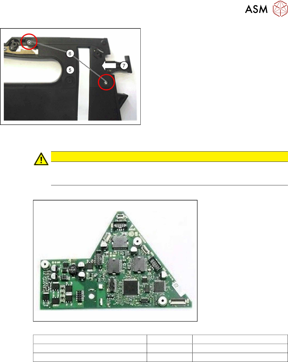
► Carefully life the cap on the foil stuffing unit(5)
into the position shown on the feeder module
base. Make sure that the flat ribbon cable hangs
out of the cap as shown.
► Fasten the cap on the foil stuffing unit at the
marked points(6) with 2 screws. Use a size 8
TORX screwdriver and 0.6 Nm for this.
► Make sure that the lock(7) on the feeder module
moves easily and that no components are
trapped or pinched.
► Fasten the left side cover (see 6.3.2 "Fitting the
Left Side Cover" [}31]).
6.16 Control board
CAUTION
Electrostatic charge
When removing and fitting the control board, observe the currently applicable ESD
guidelines.
Required spare part
Fig.20: Control board X8Smart V2
Feeder module Item no. Designation
SmartFeeder 4mmX (V2) 03101127-xx Control board X8Smart V2
SmartFeeder 4mmX (V3) 03124276-xx Control board X8Smart V3
Required tools
●
Phillips screwdriver 0.9Nm
●
TORX screwdriver 0.6Nm and 0.2 Nm, size T8
6 Repairs to SmartFeeder 4 mm X
6.16 Control board
74 Service Manual SIPLACE SmartFeeder 4 - 104 mm X 11/2017
6.16.1 Removing the control board
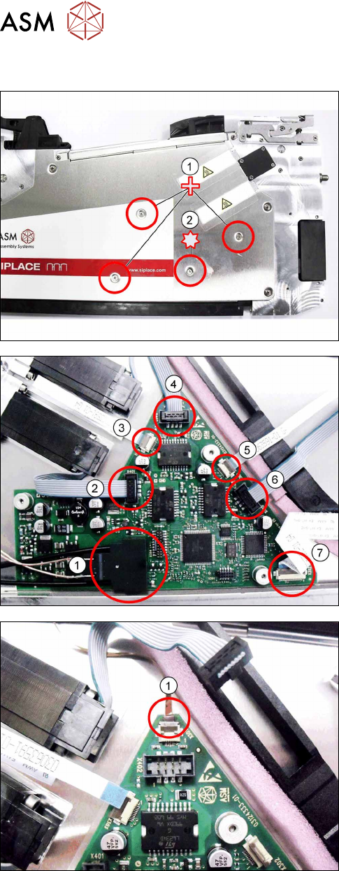
► Carefully place the feeder module with the left
side down on a stable, level and clean surface.
► Remove the three Phillips screws marked in the
picture(1), which fasten the control board to the
right side cover.
► Carefully remove the TORX screw shown in the
diagram(2), which fastens the EDIF connector to
the control board.
Use a size 8 TORX screwdriver for this.
► Carefully place the feeder module with the right
side down on a stable, level and clean surface.
► Remove the left side cover (see section 6.3.1
"Removing the Left Side Cover" [}31]).
► Remove the EDIF connector.(1)
► Loosen the 6 connections shown in the dia-
gram.(2 – 7)
► If there is a splice sensor fitted in the feeder mod-
ule, open the connection to the splice sensor
cable.(1)
► Remove the control board.