00198505-01_SM_SIPLACE_SmartFeeder_EN.pdf - 第94页
7 Repairs to SmartFeeder 8 mm X 7.6 Splice sensor 94 Service Manual SIPLACE SmartFeeder 4 - 104 mm X 11/2017 7.6.1 Replacing the Dummy with a Splice Sensor ► Place the feeder module in a stable, upright posi- tion. The d…
7 Repairs to SmartFeeder 8 mm X
7.6 Splice sensor
Service Manual SIPLACE SmartFeeder 4 - 104 mm X 11/2017 93
► Fasten the actuator axis with a fitting screw
Use a 1.5mm Allen key for this.
► Fasten the pickup window (see 7.5.2 "Fitting the
Pickup Window" [}90]).
7.6 Splice sensor
NOTICE
Removing retrofitted splice sensors
Each SmartFeeder 8mmX is prepared for using a splice sensor, although it is supplied
without the splice sensor. To re-establish this delivery state, you need to remove any retro-
fitted splice sensors before you send the feeder module back to the manufacturer for re-
pairs.
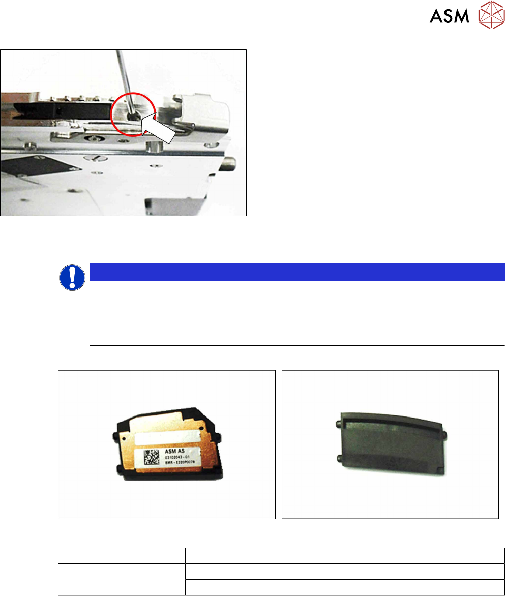
Required spare part
Splice sensor Dummy splice sensor
Feeder module Item no. Designation
SmartFeeder 8mm X 03107028 -xx Splice sensor X8Smart assy.
03104558 -xx Dummy splice sensor X8Smart
Required tools
●
TORX screwdriver 0.6Nm, size T8
7 Repairs to SmartFeeder 8 mm X
7.6 Splice sensor
94 Service Manual SIPLACE SmartFeeder 4 - 104 mm X 11/2017
7.6.1 Replacing the Dummy with a Splice Sensor
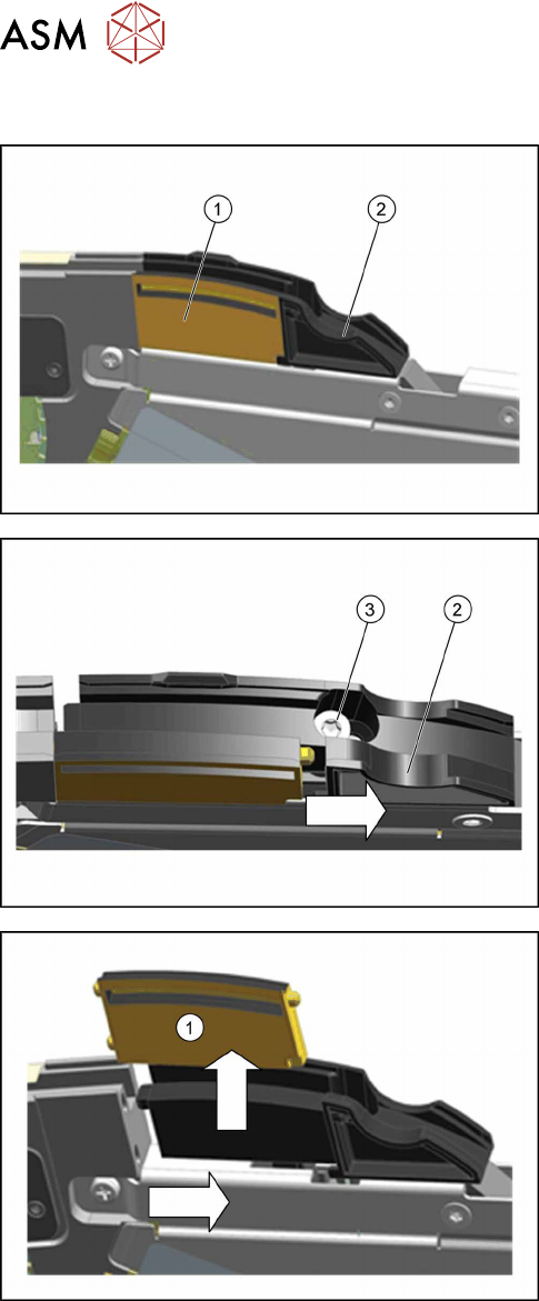
► Place the feeder module in a stable, upright posi-
tion.
The dummy splice sensor(1) is located behind the
pickup window and is held by the "splice sensor filling
piece"(2).
► Loosen the TORX screw(3), with which the filling
piece(2) is fixed, until you can move the filling
piece.
► Move the filling piece in the direction of the arrow
until you reach the right-hand stop.
► Push the dummy splice sensor (1) next to the
filling piece until the two pins on the front of the
dummy is free.
► Pull the dummy up and out.
7 Repairs to SmartFeeder 8 mm X
7.6 Splice sensor
Service Manual SIPLACE SmartFeeder 4 - 104 mm X 11/2017 95
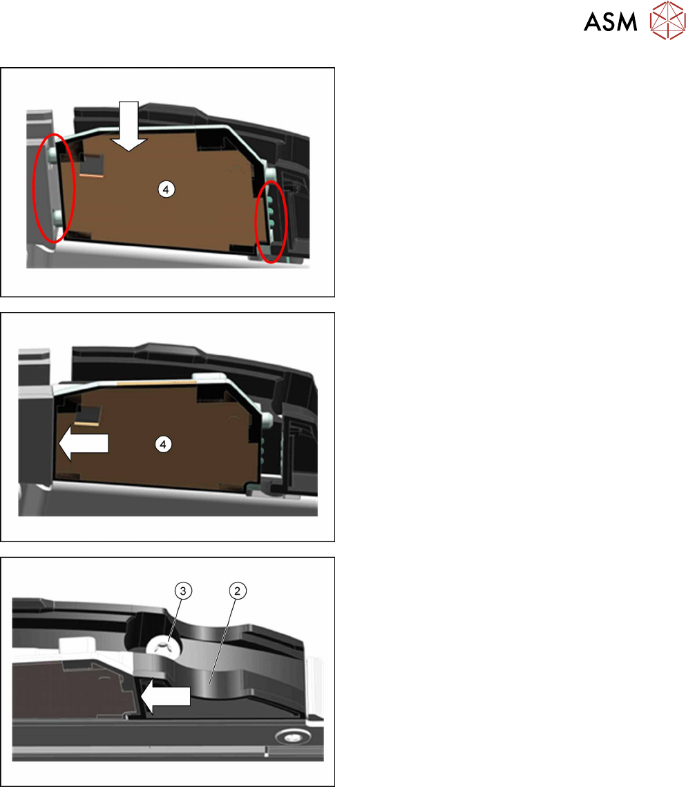
► Insert the splice sensor(4) in place of the
dummy, as shown.
Make sure that the 2 fixture pins point forwards
and the 3 contact pins point backwards.
► Push the splice sensor(4) forwards, in the direc-
tion of the arrow, as far as the stop.
► Push the filling piece(2) in the direction of the ar-
row, towards the splice sensor, as far as the stop.
► Fix the filling piece with the TORX screw(3) and
0.6Nm.
The splice sensor is automatically contacted by the
board on the filling piece and is then recognized by the
software.