Vakuumtooling Neology HF3.pdf - 第29页
Installation instructions Vacuum Tooling Neology (00166109-01) SIPLACE HF3 02/2005 Edition 29 Circuit diagram for wiring the option 2 2 00166109-01 Vacuum tooling wiring Vaacuum toolin g circuit d iagram Note!
Installation instructions Vacuum Tooling Neology (00166109-01) SIPLACE HF3
02/2005 Edition
28
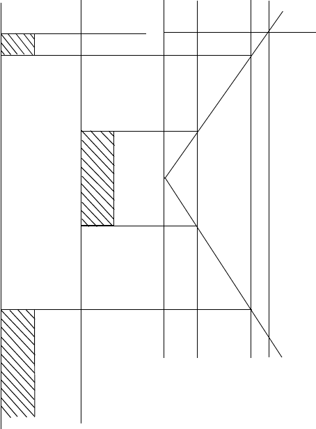
Working principle of the vacuum switch: 2
2
For programming, see 1.6.3. 2
If the vacuum threshold cannot be reached, then the placement process cannot be started. 2
Once the placement process has ended, the vacuum must be reduced to the set threshold (150
mbar) so that the lifting table can move down. 2
The vacuum threshold is only checked immediately after the lifting table has moved up. 2
A drop in vacuum during placement cannot be detected. 2
0 bar2
- 1 bar1
A 21
H 11
Output 11
Output 21
- 150 mbar1
- 700 mbar1
if 1==>
signal that
placement may start 1
if 1==>
signal that the lifting
table may be lowered 1
Installation instructions Vacuum Tooling Neology (00166109-01) SIPLACE HF3
02/2005 Edition
29
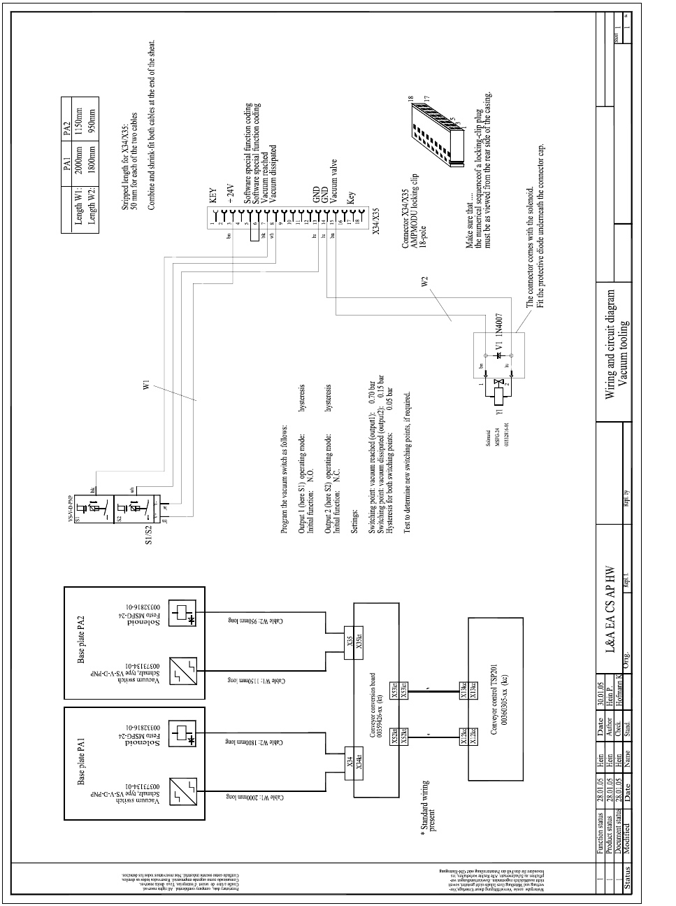
Circuit diagram for wiring the option 2
2
00166109-01
Vacuum tooling wiring
Vaacuum tooling circuit diagram
Note!
Installation instructions Vacuum Tooling Neology (00166109-01) SIPLACE HF3
02/2005 Edition
30
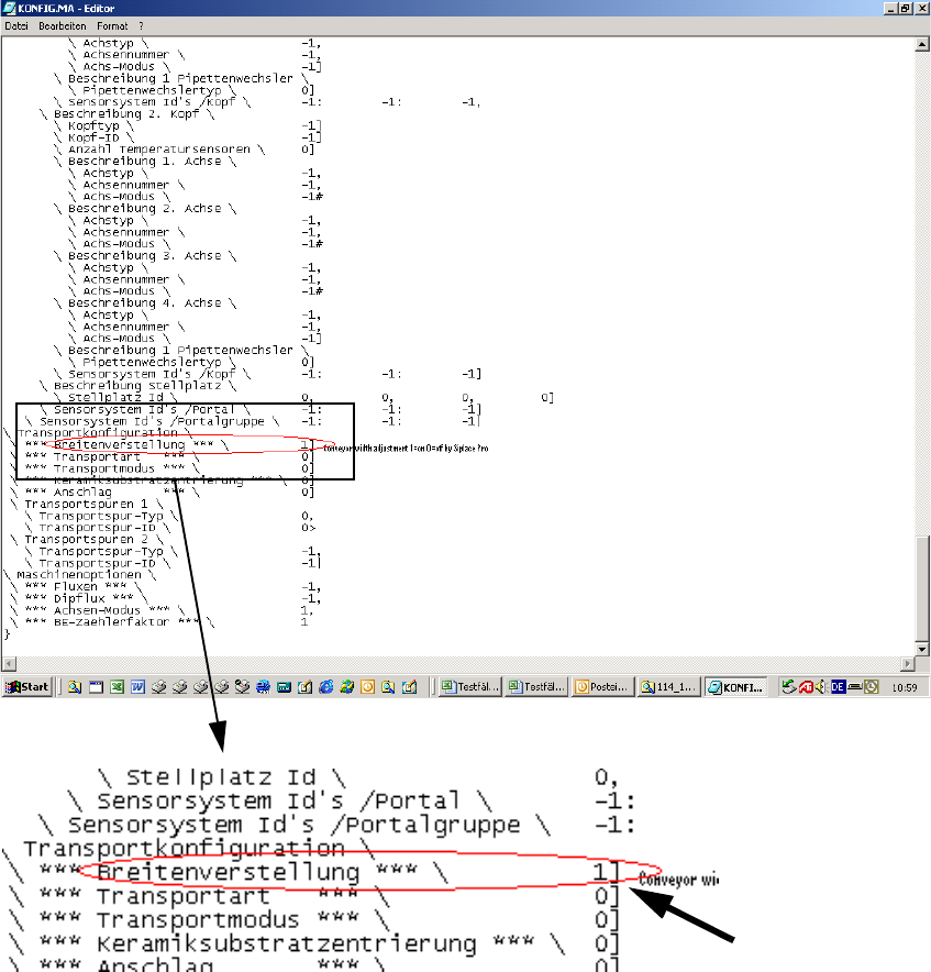
To avoid a crash situation between the conveyor and the vacuum tooling, the automatic width ad-
justment must be deactivated using SIPLACE Pro. 2
This involves changing Config.ma in the SRDaten/SRCMA directory. 2
2
2
2
Change from 1 to 0 2