Vakuumtooling Neology HF3.pdf - 第34页
Installation instructions Vacuum Tooling Neology (00166109-01) SIPLACE HF3 02/2005 Edition 34 2 2 2 2 2 2 2 St o p v a l v e on mainte nance unit 2 The se t press ure shou ld be b etween 5 .5 and 6 bar . 1
Installation instructions Vacuum Tooling Neology (00166109-01) SIPLACE HF3
02/2005 Edition
33
2.5.1 Compressed air supply
Direct connection to the HF pneumatic unit is not possible, since this would exceed the specified
air consumption. An additional maintenance unit must therefore be installed in the pneumatic unit.
The customer must provide an additional compressed air line. 2
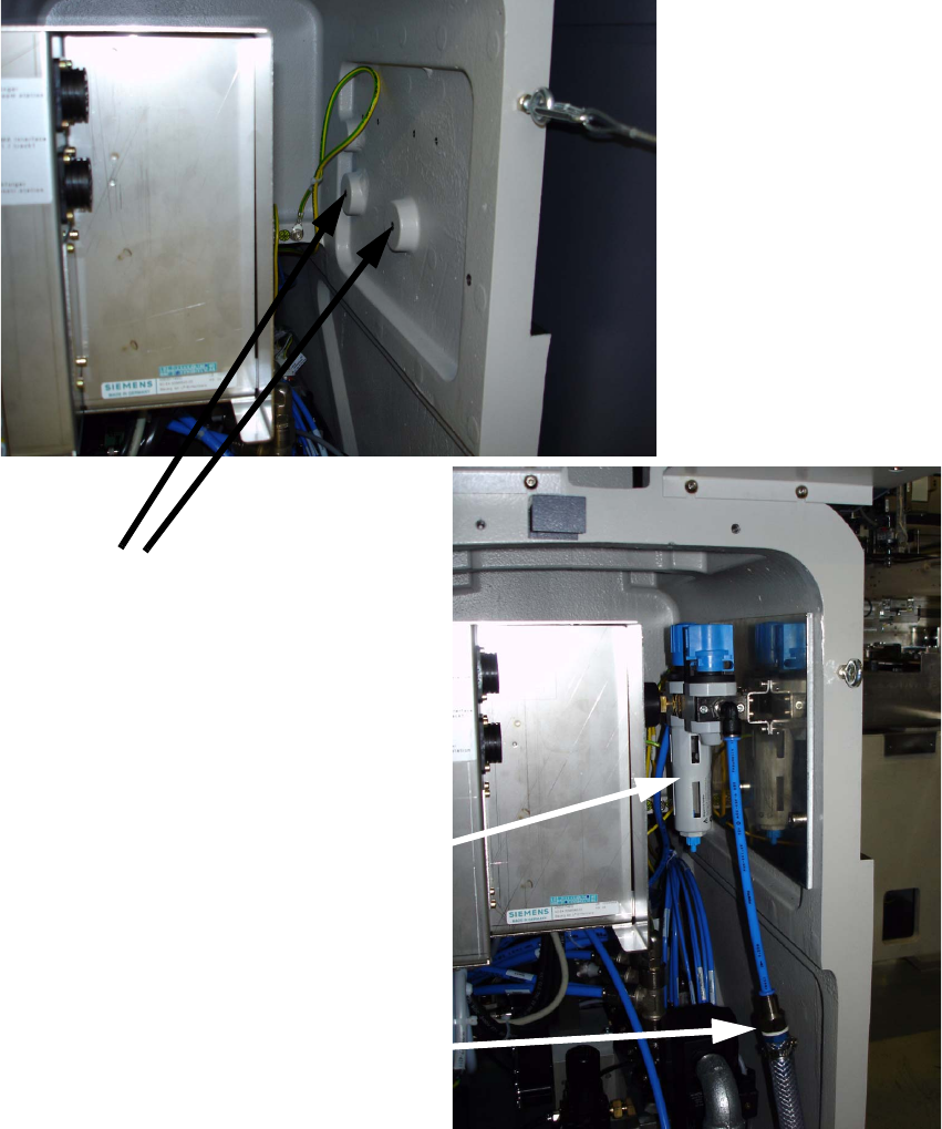
The maintenance unit is fitted in the pneumatic unit on a mounting plate. 2
2
Fixing the
mounting plate 2
Additional maintenance unit
in the pneumatic block 1
Additional external
air connection 1
Installation instructions Vacuum Tooling Neology (00166109-01) SIPLACE HF3
02/2005 Edition
34
2
2
2
2
2
2
2
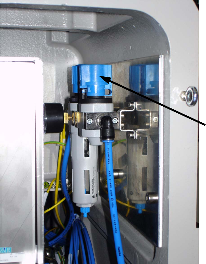
Stop valve
on maintenance
unit 2
The set pressure should be between 5.5 and 6 bar. 1
Installation instructions Vacuum Tooling Neology (00166109-01) SIPLACE HF3
02/2005 Edition
35
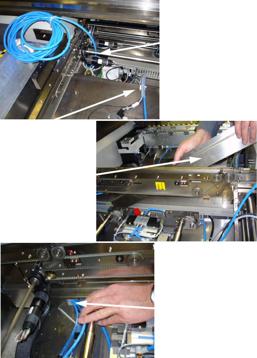
2.5.2 Hoses inside the machine
2
Compressed air hose on the
maintenance unit 2
Running compressed air hose
in the cable duct (placement area
Removing panel over the
cable duct (PA 1) 1
Running cables and hoses
in placement area 2 1