00191474-02.pdf - 第22页
Cable mounting plate on t he head board Retrof it instructions HS -50 1 1/99 edition 22 6 Att aching the V elcro fasteners and roun d cable holder to the component vision module Å Clean th e adhesiv e surfaces of the rev…
Retrofit instructions HS -50 Cable mounting plate on the head board
11/99 edition
21
5
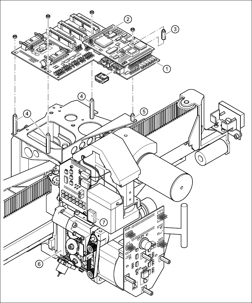
Fig. 5 - 1 Dismantling the head board and fixing parts
5
5
5

Cable mounting plate on the head board Retrofit instructions HS -50
11/99 edition
22
6 Attaching the Velcro fasteners and round cable
holder to the component vision module
Å Clean the adhesive surfaces of the revolver head identified by item 7 in Fig. 5 - 1 and item 1 –
4 in Fig. 6 - 1 using a clean, lint-free cloth moistened with ethyl alcohol.
PLEASE NOTE: 6
The adhesive surface must be free of oil and grease. 6
Å Remove the protective film from the adhesive surfaces of the Velcro fasteners.
Å Place the Velcro fasteners at the indicated points on the revolver head (item 7 in Fig. 5 - 1 and
item 1 – 3 in Fig. 6 - 1) and press down lightly.
Å Remove the protective film from the side of the Velcro fastener facing the ribbon cable.
CAUTION 6
Use your index finger and press the ribbon cable only lightly against the adhesive surfaces.
Otherwise you may break the cable, which would cause faults in the revolver head. 6
Å Remove the protective film from the adhesive surface of the round cable holder and press
down lightly to fix it to item 4 in Fig. 6 - 1.
Å Snap the vacuum hose into the clip of the round cable holder.
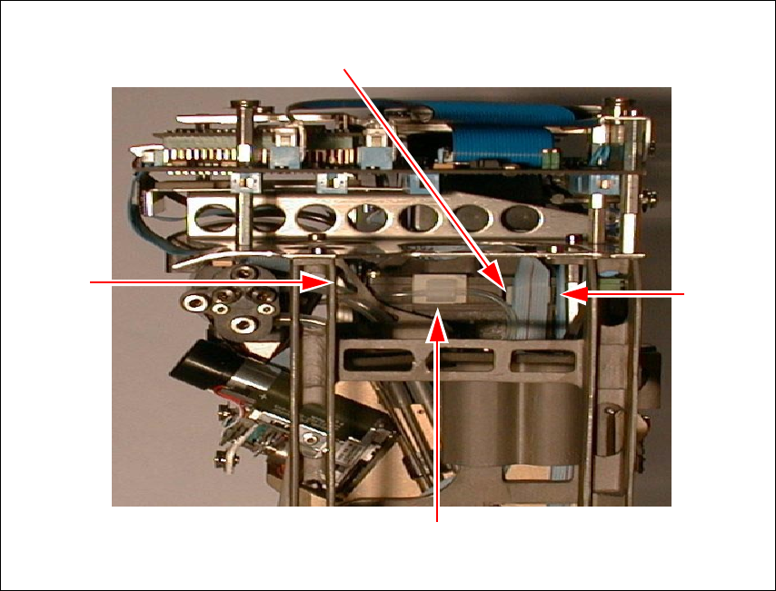
Retrofit instructions HS -50 Cable mounting plate on the head board
11/99 edition
23
6
Fig. 6 - 1 Additional Velcro fasteners on the revolver head
(1) Velcro fastener for the ribbon cable of the ‘Discard’ valve positioning drive
(2) Velcro fastener for the ribbon cable of the ‘Pick up/Insert’ valve positioning drive
(3) Velcro fastener for the ribbon cable of the turning station/DLM1
(4) Round cable holder for the vacuum hose
(1)
(2)
(3)
(4)