00191474-02.pdf - 第24页
Cable mounting plate on t he head board Retrof it instructions HS -50 1 1/99 edition 24 7 Fitti ng the n ew fixing p art s, cable mountin g plate and head board Fit the fo llowing fix ing parts in the or der describ ed b…
Retrofit instructions HS -50 Cable mounting plate on the head board
11/99 edition
23
6
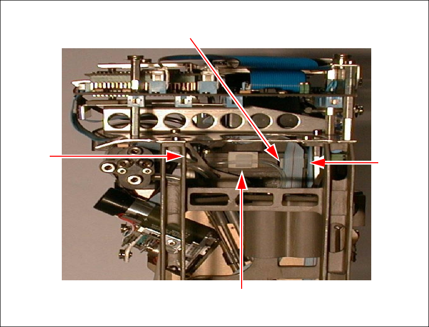
Fig. 6 - 1 Additional Velcro fasteners on the revolver head
(1) Velcro fastener for the ribbon cable of the ‘Discard’ valve positioning drive
(2) Velcro fastener for the ribbon cable of the ‘Pick up/Insert’ valve positioning drive
(3) Velcro fastener for the ribbon cable of the turning station/DLM1
(4) Round cable holder for the vacuum hose
(1)
(2)
(3)
(4)
Cable mounting plate on the head board Retrofit instructions HS -50
11/99 edition
24
7 Fitting the new fixing parts, cable mounting plate
and head board
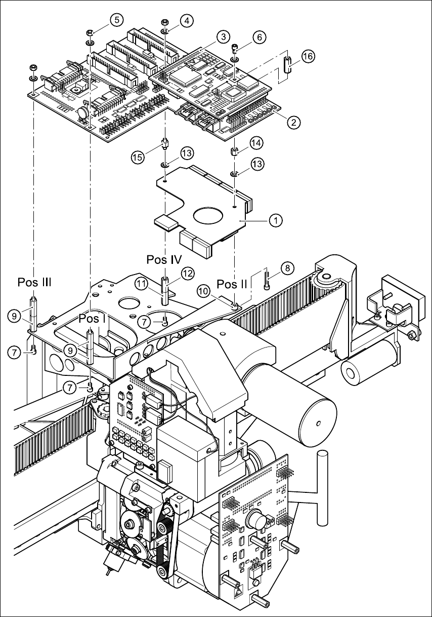
Fit the following fixing parts in the order described below (see Fig. 7 - 1): 7
– At pos. I:
M3x5 fillister head screw, item 7
2x M3x18 spacer bolts (internal thread/external thread), item 9
– At pos. III:
M3x5 fillister head screw, item 7
2x M3x18 spacer bolts (internal thread/external thread), item 9
– At pos. IV:
M3x5 fillister head screw, item 7
M3x15 spacer bolt, (internal thread/internal thread), item 11
M3x14 spacer bolt (internal thread/external thread), item 12
– At pos. II:
M3x20 fillister head screw, item 8
Spacer sleeve, Ø 3.2x6x4, item 10
Cable mounting plate, item 1
M3 washer, item 13
M3x5 spacer bolt, (internal thread/internal thread), item 14
Å Tighten the spacer bolts.
– At pos. IV:
M3 washer, item 13
M3x5 spacer bolt, (external thread/external thread), item 15
Å Tighten the spacer bolts.
Å Place the holes in the head board (item 2) over the threaded pins of the spacer bolts.
Å Check that the head board is lying flat on all the spacer bolts.
– At pos. II:
Å Screw the M3x15 spacer bolt (internal thread/internal thread), item 16 onto the threaded
pin.
Å Tighten the bolt. Make sure that you do not damage the head board.
Retrofit instructions HS -50 Cable mounting plate on the head board
11/99 edition
25
7
Fig. 7 - 1 Fitting the fixing parts and cable mounting plate