00191474-02.pdf - 第26页
Cable mounting plate on t he head board Retrof it instructions HS -50 1 1/99 edition 26 A TTENTION 7 Before a ttaching th e head pr ocessor b oard, ch eck th at 7 - none of the pins o n the head board (item 2 in Fig. 7 -…
Retrofit instructions HS -50 Cable mounting plate on the head board
11/99 edition
25
7
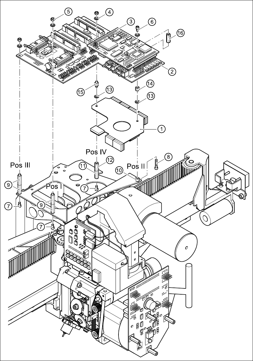
Fig. 7 - 1 Fitting the fixing parts and cable mounting plate
Cable mounting plate on the head board Retrofit instructions HS -50
11/99 edition
26
ATTENTION 7
Before attaching the head processor board, check that 7
- none of the pins on the head board (item 2 in Fig. 7 - 1) are bent
- the plugs of the head processor board are seated correctly on the rows of pins on the head
board. 7
Å Carefully press the head processor board against the head board until the plugs of the head
processor board come to rest against the head board.
Å Use the M3 washers (item 4) and M3 nuts (item 5) to fix the head processor board at positions
I/III and IV.
Å Use the M3 washer (item 4) and M3x5 fillister head screw (item 6) to fix the head processor
board at position II.
Å Secure all the screws and nuts with Loctite 243.
Å Attach all the cables once more.
Å Remove the protective paper from the adhesive tapes (items 2, 3, 5 and 6 in Fig. 1 - 1) and
carefully press the ribbon cable against the adhesive tapes.
CAUTION 7
Use your index finger and press the ribbon cable only lightly against the adhesive surfaces.
Otherwise you may break the cable, which would cause faults in the revolver head. 7
Å Snap the black dp motor cable onto the round cable holder (item 4 in Fig. 1 - 1).
8 Function test
Å Remove all tools and other parts from the placement system.
Å Close the protective covers.
Å Start the placement system and watch the reference run.