ALD6700S-Brochure-LR - 第3页
Beyond Innovation Easy and fast, wizard based programming Structured and clearly defined access level Alerts and feedback for continuous printing process improvement Communication with the pick and place systems • Operat…
Beyond Innovation
The unique optical system developed by ALeader delivers an accurate, reliable 3D
measurement and top-quality high-resolution 2D image
• Bi-directional structured light (advanced phase-shifting
digital projection system, developed in-house)
• Multi-directional (360˚ horizontal, 0-90˚ vertical)
LED illumination system
• High-speed camera
Simultaneous 2D and 3D inspection guarantees full inspection coverage with
the most accurate measurement of the paste deposits height, area and volume
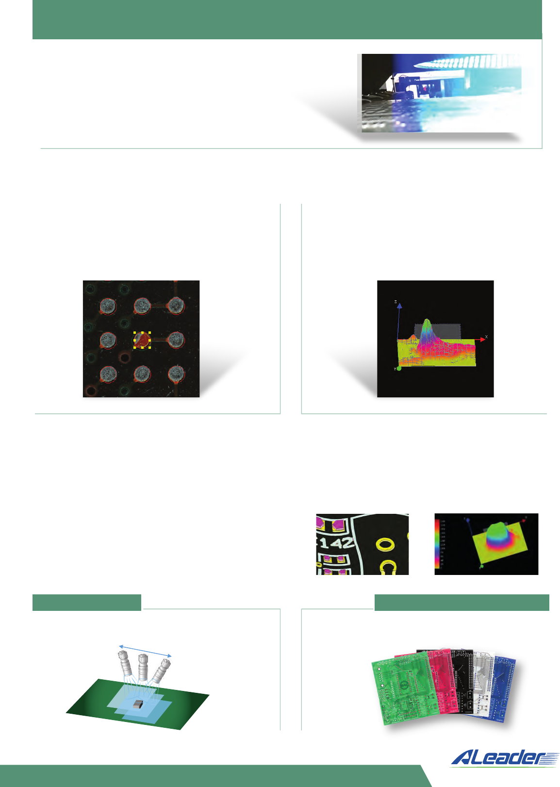
The superior high-resolution image, generated
by the high-speed camera and the unique
lighting system, clearly distinguishes between
the pastes, pads, silkscreen and the board.
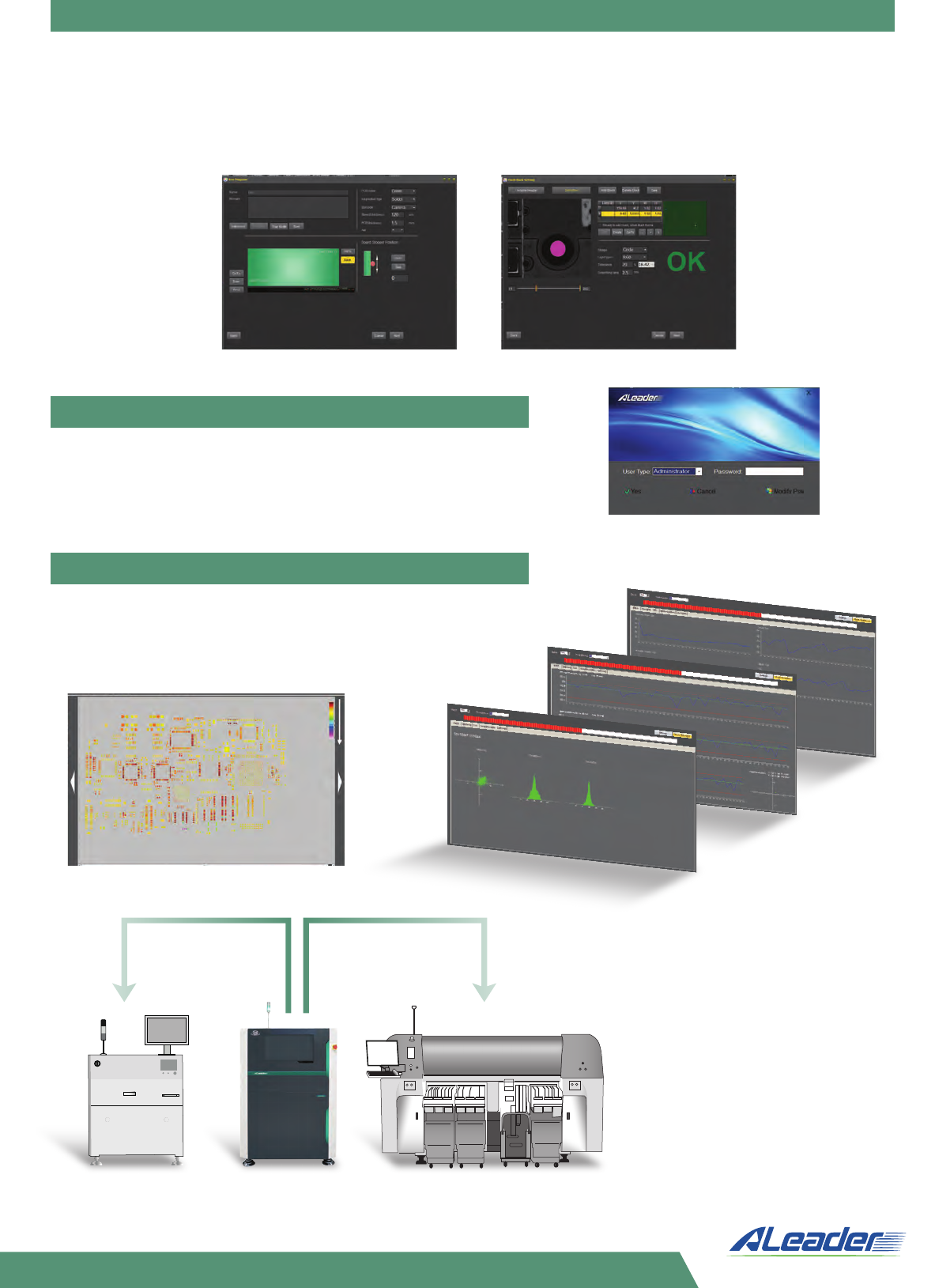
Innovative, real-time automatic warpage compensation and measurement floor
recognition method. The system identifies the pads as a zero level for the paste height
measurement for each board and FOV. Such a capability completely eliminates the
influence of PCB warpage on the inspection result. The process is completely automatic
and user-independent, no bare board or any special procedures are required.
PCB warpage does not affect the measurement
result, system provides precise paste height
from the pad level
Precise height measurement based on Phase
Measurement Profilometry (PMP).
Bi-directional phase shifting projection system
ensures accurate and noise resistant
measurement of the paste height and volume.
FOV uniformity Insensitivity to PCB color
Over 90% brightness uniformity across the FOV. High
measurement accuracy is consistent throughout all
parts of the PCB
Accurate measurement
– same result
ALeader’s SPI advanced optical system guarantees
the same superior level of performance on PCBs of
any color
Beyond Innovation
Easy and fast, wizard based programming
Structured and clearly defined access level
Alerts and feedback
for continuous
printing process
improvement
Communication
with the pick and
place systems
• Operator – Production, Process
• Programmer – Production, Process, Setup
• Administrator – Production, Process, Setup, Config,
HW and Diagnostic
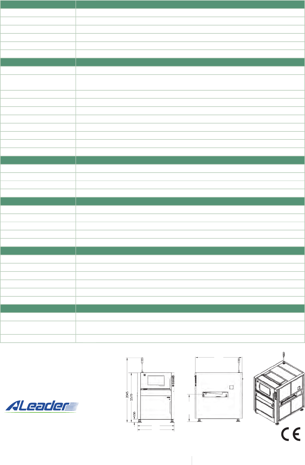
Real-time built-in SPC as a standard
• Height map for each PCB
• Real-time monitoring charts for height, volume, area and offset
• History review and analysis
• Closed loop with the printer
• Communication with the P&P
• Alerts
• Less than 5 min to start production for a new product, with a friendly and intuitive user interface.
• Takes less than an hour to train a new user to program and operate the system.
• Possible to create a program without Gerber using a good board sample only (auto programming).
• Global quality settings based on paste size and stencil thickness are automatically adopted for
each new program, delivering the same high-quality programs despite having been written by a
different user.
Functional specification
Inspection method
Camera
Lighting system
Program creation
Inspection coverage
Operation system
Inspection board specification
PCB type
PCB size range
PCB thickness range
Clamping system edge clearance
PCB weight
Underside/topside clearance
Min paste size
Max paste size
Max measurement height
Min paste pitch
Inspection performance
Resolution/ranges/speed
Height Resolution
Reproducibility
GR&R
Features and options
Special features
Barcode system
Server mode
Remote control
Additional Options
Hardware
Conveyor
Conveyor direction/time
X/Y driver
Power supply
Compressed air
Equipment communication
Weight
Dimensions
Conveyor height
Dimension and Weight
12M pixel high-speed camera. Telecentric lens
Top and 360˚ steep LED light; bi-directional structured light projection
Import Gerber (274X, 274D) file , auto programming (w/out Gerber)
Volume, area, height, offset, insufficient, excessive, bridge, joint, contamination, etc…
Windows 10 Professional 64 bit
All colors and all pad finishes
Min 50 x 50mm, Max 450 x 500mm (ALD6710S) 650 x 710mm (ALD6730S) 1500 x 450mm
(ALD6750S) 450 x 330/610mm (ALD6710D) 650 x 330/610mm (ALD6730D)
0.3mm to 5mm
Top 2.5mm, bottom 3mm
up to 3 kg
60/30mm (ALD6710S, ALD6730S), 65/40mm (ALD8750S), 30/40mm (ALD6710D, ALD6730D), 30/65mm (ALD6750S)
0.125mm x 0.125mm
10mm x 10mm
1000μ
100μ
15µ, FOV: 61.44 x 45mm (7µ, FOV 28.62 x 21mm - option), Test speed 400 ms/FOV
0.25μ
Height <1% at 3σ, Volume <1% at 3σ
<10% at 6σ
Supports auto change program, multiboards and multiprograms inspection modes
Auto read barcode 1D and 2D. External reader reads back side barcode (option)
Central server, multiple machines, data handling
SPC repair station, Offline program, External barcode scanner
Screw and AC servo driver, precision 0.25μ; PCB fix, camera moves X/Y
Left to right or right to left in/out time 4 sec
AC230V 50/60Hz <1.5KVA
0.4-0.8 MPA
SMEMA
920 kg
880-950mm
Flat belt conveyor, automatic clamp (pneumatic), auto load and unload, automatic width adjustment
Remote control through TCP/IP for verification, system operation and program adjustment
Phase Measurement Profilometry
1000x1340x1610mm (ALD6710S), 1000x1540x1610mm (ALD6710D), 1200x1540x1610mm
(ALD6730S, ALD6730D), 2100x1210x1550mm (ALD6750S)
Beyond Innovation
ALeader Vision Technology Co., Ltd.
Manufacturing
Dongguan city, Guangdong province 523128, China
ALeader Europe Ltd.
International Marketing- Training Center - Support Center
Industrial Zone Netser Sereni 7039500, Israel
Tel: +972-89208844 Fax: +972-89207711 | www.aleader-europe.com
08.2021
Above specificaons are subject to change without noce. Images used in the brochure are for illustrave purposes only
System footprint dimensions are shown for model ALD6730S.
For other models please refer to the specificaon table
1180
1200
880~950
1540