MV-9_Chapter 5. Teaching.pdf - 第114页
MV -9 Use r Manual 5-1 1 4 [Figure 5- 124 IC inspection window creation screen] 8) Default p arameter [Figure 5- 125 IC/ Bridge in s pection default p arameter] Reference name Refer to „ r eference na m e i n „5.3.1 …
错误!使用“开始”选项卡将 제목 2 应用于要在此处显示的文字。错误!使用“开始”选项卡将 제목 2 应用
于要在此处显示的文字。 .
5-113
search range for others. For example, set X-side search range to be large search range
of Y-side search range to be small
For compensation window, use general mounting window. Like bridge, group them into a
component to make compensation window.
Draw small IC component
In case of IC component of which all components get into one frame, draw bridge for
each lead, and set compensation window and group into a component at one edge.
For search range of compensation window, set about 20 of value for both of width and
height.
Draw large IC component
Conduct individual teaching for large IC component by moving frame.
2 4 3 5 A B C
2 4 3 5 A B C
[Figure 5-122 IC component teaching example]
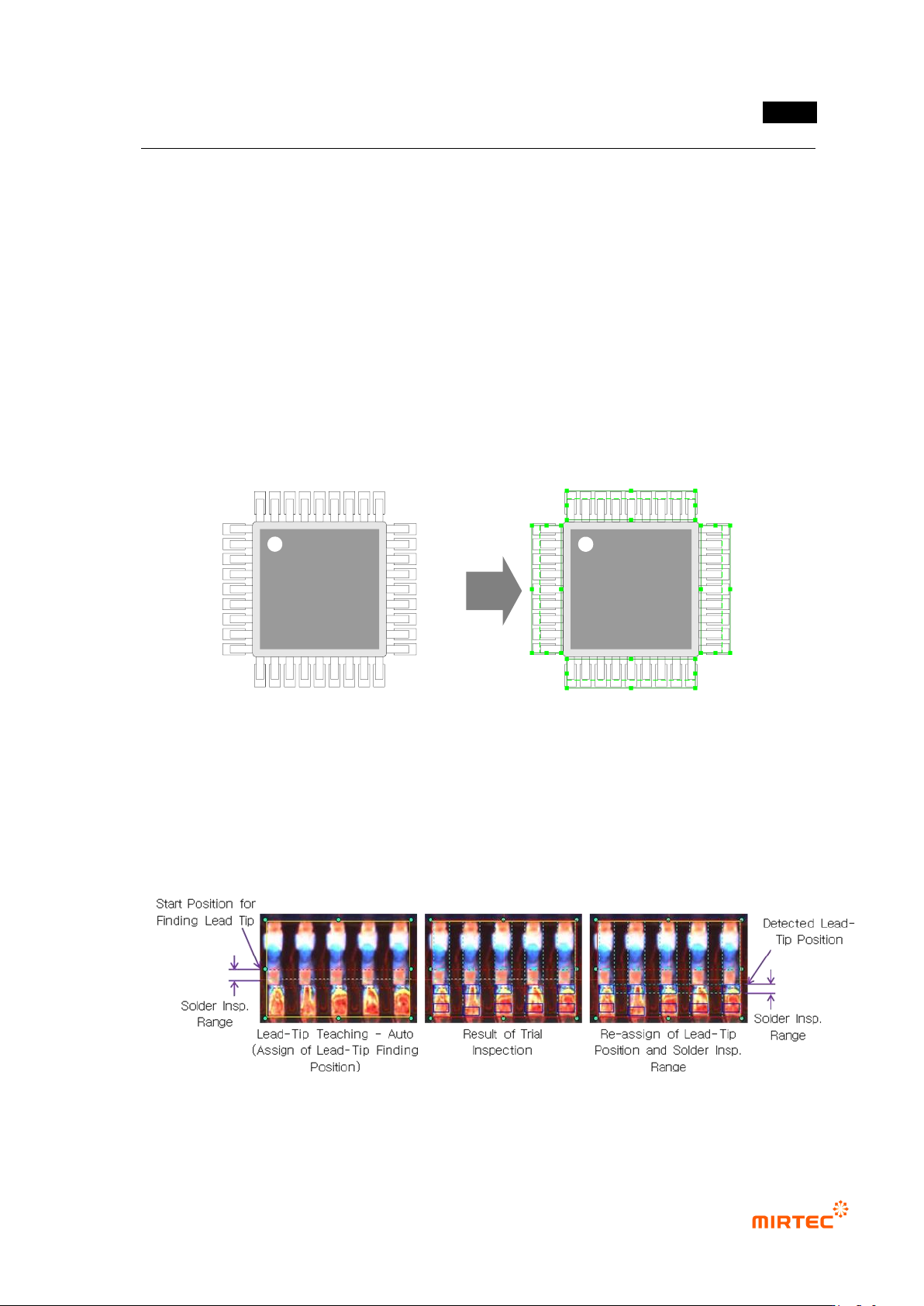
Lead tip display
If lead tip auto search option is set for initial teaching, position of solder inspection width
will be drawn based on lead tip search start position. However, position of solder
inspection width will be displayed based on lead tip position found from manual inspection
more than 1 time.
[Figure 5-123 lead tip auto search]
MV-9 User Manual
5-114
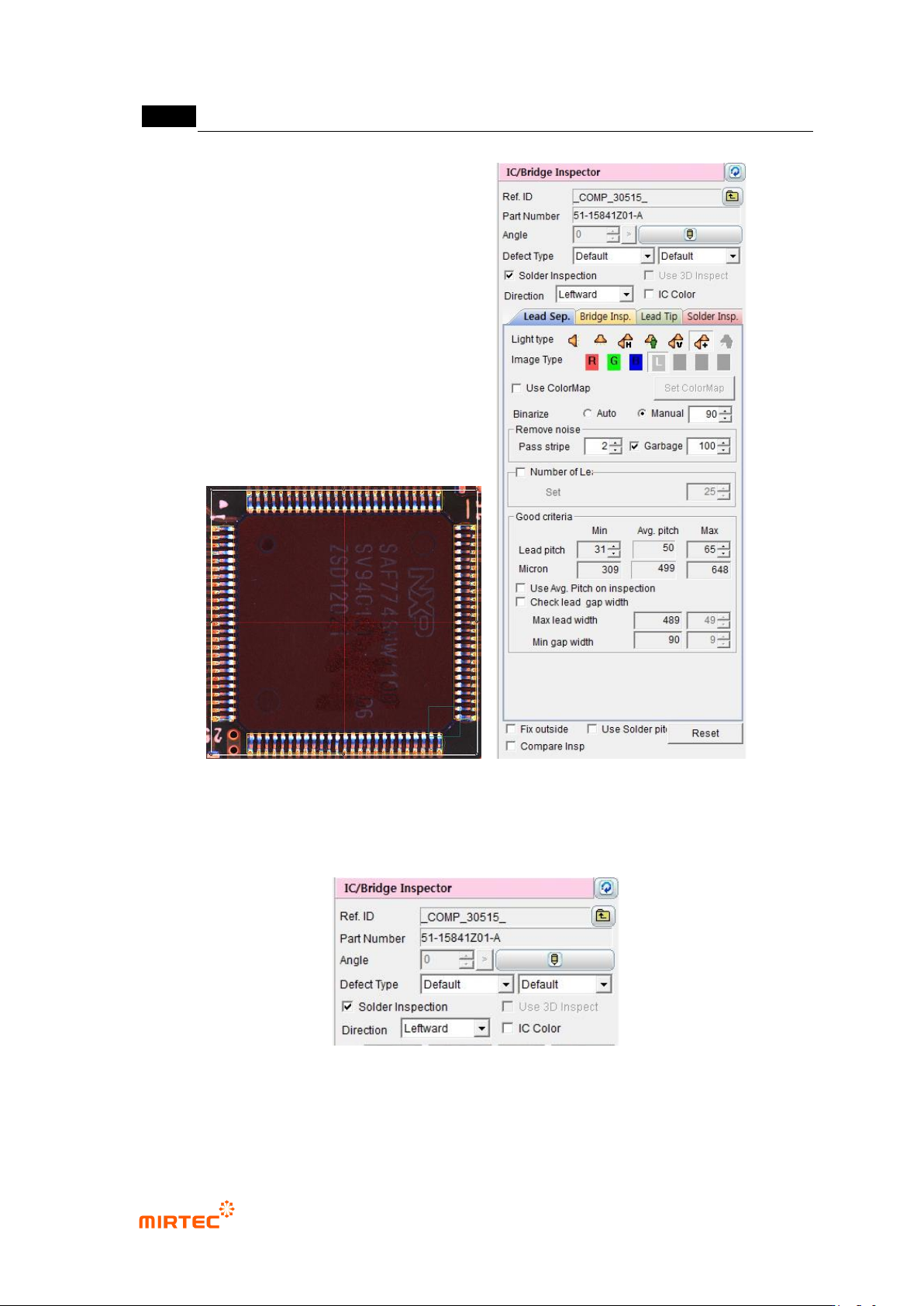
[Figure 5-124 IC inspection window creation screen]
8) Default parameter
[Figure 5-125 IC/Bridge inspection default parameter]
Reference name
Refer to „reference name in „5.3.1Solder amount inspection
错误!使用“开始”选项卡将 제목 2 应用于要在此处显示的文字。错误!使用“开始”选项卡将 제목 2 应用
于要在此处显示的文字。 .
5-115
Set whether IC/Bridge inspection window conducts solder amount inspection for fillet part
or not. „Lead tip‟ tap and „solder amount inspection‟ tap will be activated when this option
is set.
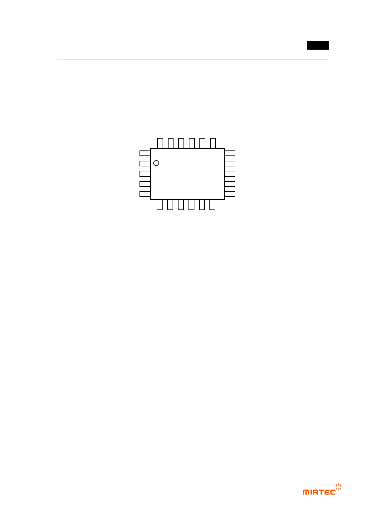
Direction
Direction of lead spread based on IC component body.
[Figure 5-126 IC component shape]
IC color
Check at this function for lifted lead inspection by interlocking color inspection window
with IC Bridge inspection window.
For normal range for IC color inspection, set it using pixel ratio (upper limit) and IC
average ratio inspection+ (%) (lowest limit) in color inspection window.
9) Common parameter
For smooth conduction of the relevant inspection or area setting, there are items to
adjust parameter on each tap. The followings are parameters commonly used on each
tap.
Binarization boundary value
Auto: program automatically set binarization value for image binarization.
Manual: users directly set binarization value for image binarization.
Noise removal – stripe width (Pass Stripe)
This is used to remove length direction noise component of lead from binarized image.
The larger value, the thinner lead width.
Upward
Rightward
Leftward
Downward