MV-9_Chapter 5. Teaching.pdf - 第143页
错误 ! 使用“开始” 选项卡将 제목 2 应用于要在此处显示的文字。 错误 ! 使用“开始”选项卡将 제목 2 应用 于要在此处显示的 文字。 . 5- 143 [Figure 5- 171 T eachin g example of color inspection window] 3) Common pa rameter of color in spection w indow Reference name - Refer t…
MV-9 User Manual
5-142
[Figure 5-169 color inspection window creation screen]
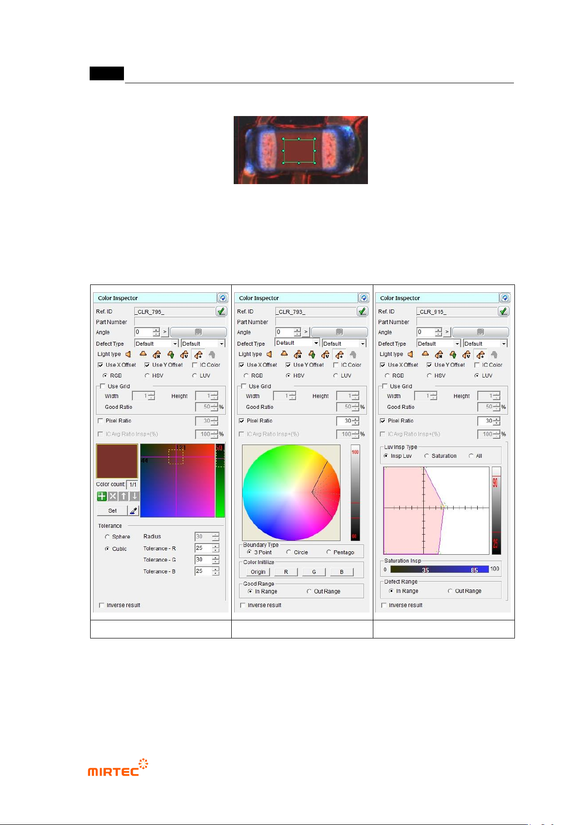
RGB color coordinator
HSV color coordinator
LUV color coordinator
[Figure 5-170 Color inspection parameter according to color coordinator]
2) Teaching example of representative component
错误!使用“开始”选项卡将 제목 2 应用于要在此处显示的文字。错误!使用“开始”选项卡将 제목 2 应用
于要在此处显示的文字。 .
5-143
[Figure 5-171 Teaching example of color inspection window]
3) Common parameter of color inspection window
Reference name
- Refer to „reference name in „5.3.1 mounting inspection window‟ excepting shape.
- Name is created in „_CLR_1_‟ format. „CLR‟ means creation order of Color and the number
means color inspection window.
Component name
- Refer to „component name in '5.3.1 light type
- Basically, select horizontal + vertical light for light type. However, select –light in which
color of component inspection area is clear.
Rotation angle
- Refer to „rotation angle in '5.3.1 mounting inspection window‟.
Defect type
- Refer to „defect type in '5.3.1 mounting inspection window‟.
light type
- Basically, select horizontal + vertical light for light type. However, select –light in which
color of component inspection area is clear.
X coordinate compensation
- Select whether to conduct X coordinate compensation for position deviation of mounting
window for compensation of position set at the relevant component.
Y coordinate compensation
- Select whether to conduct X coordinate compensation for position deviation of mounting
window for compensation of position set at the relevant component.
IC color
- Check at this option for lead color inspection by interlocking with IC Bridge inspection
window. (Refer to IC Bridge inspection.)
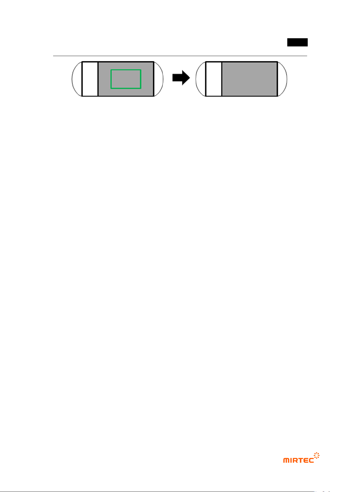
Use grid inspection
- Divide the relevant window with grid and individually inspect each area.
MV-9 User Manual
5-144
- Width/height: To set width/height grid value, divide inside of the window into given value
and conduct color inspection for each area.
- Inspection for individual segmentation region is conducted and calculate normal ratio with
average RGB value for each area.
- Normal ratio
If grid inspection result is below value set at normal ratio, judge as defect. If it is
above value set at normal ratio, judge as good.
If ratio of number of normal grid is above setting normal ratio when grid inspection
is used among total number of grid set in inspection area, setting inspection area
will be judged as good. (If differ from good/defect judgment criteria while using grid
inspection in soldering inspection.)
For example, grid is divided into width 4 and height 4 and total 16 grids are created,
and if grid that is judged as normal is more than 8 when normal ratio is set to 50%,
inspection area will be judged as normal.
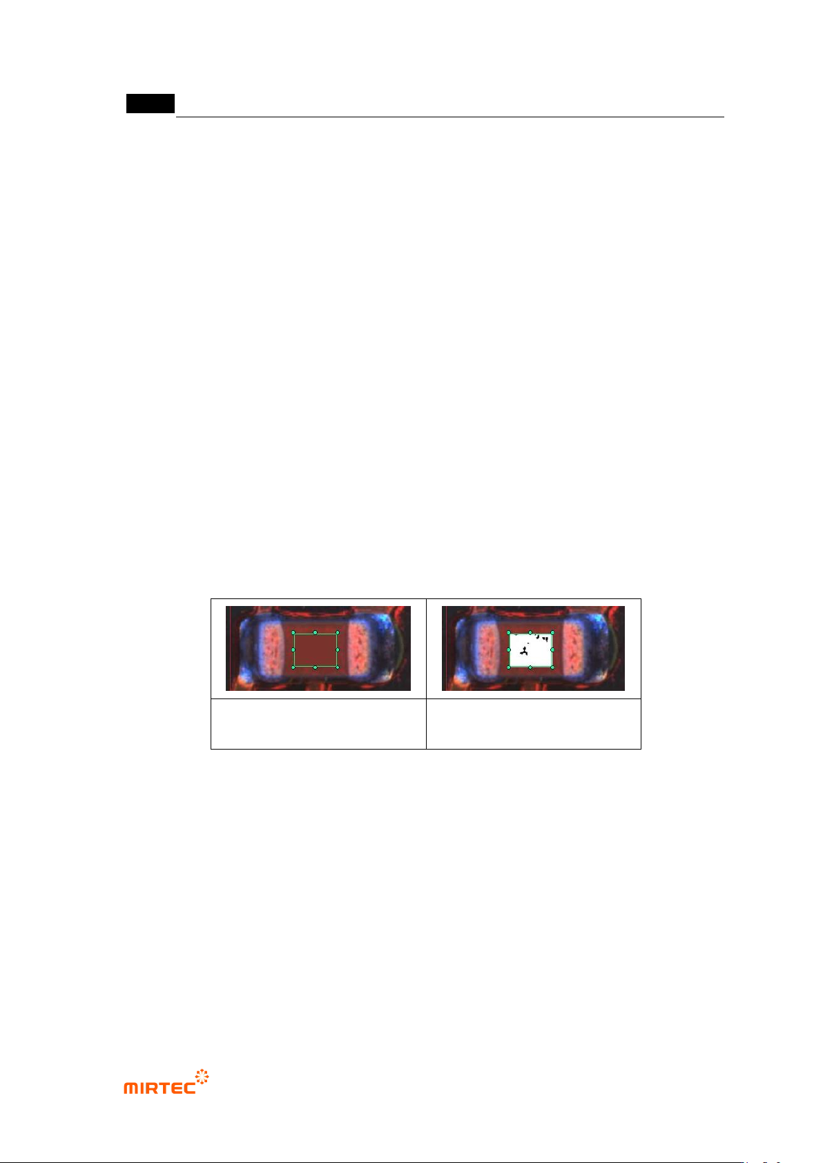
Pixel ratio
- Conduct good/defect judgment using ratio of pixel relevant to color relevant to color
registered in teaching window.
- Preview for which pixel ratio is not selected will display average color of teaching region.
Preview for which pixel ratio is selected will display pixel with color of normal range or
normal boundary region in white.
preview when pixel ratio is
selected
preview when pixel ratio is
selected
[Figure 5-172 preview image in color inspection window]
IC average ratio inspection + (%)
- This is activated when IC color and pixel ratio is selected. Conduct pixel ratio inspection for
lead separation area in IC Bridge inspection and intersection area in color inspection
window.
- In case of occurrence of lifted defect, detect defect using characteristic of which color is
changed in lead area. (Refer to IC Bridge inspection.)
Judge defect as normal
- This function is to reverse good/defect judgment result.