MV-9_Chapter 5. Teaching.pdf - 第184页
MV -9 Use r Manual 5- 184 [Figu re 5- 226 Example of normal boundary region selection] chip i m age electrode b inari zation setting pad binarization setting [Figu re 5- 227 A d justment example of chip electrode and pad…
错误!使用“开始”选项卡将 제목 2 应用于要在此处显示的文字。错误!使用“开始”选项卡将 제목 2 应用
于要在此处显示的文字。 .
5-183
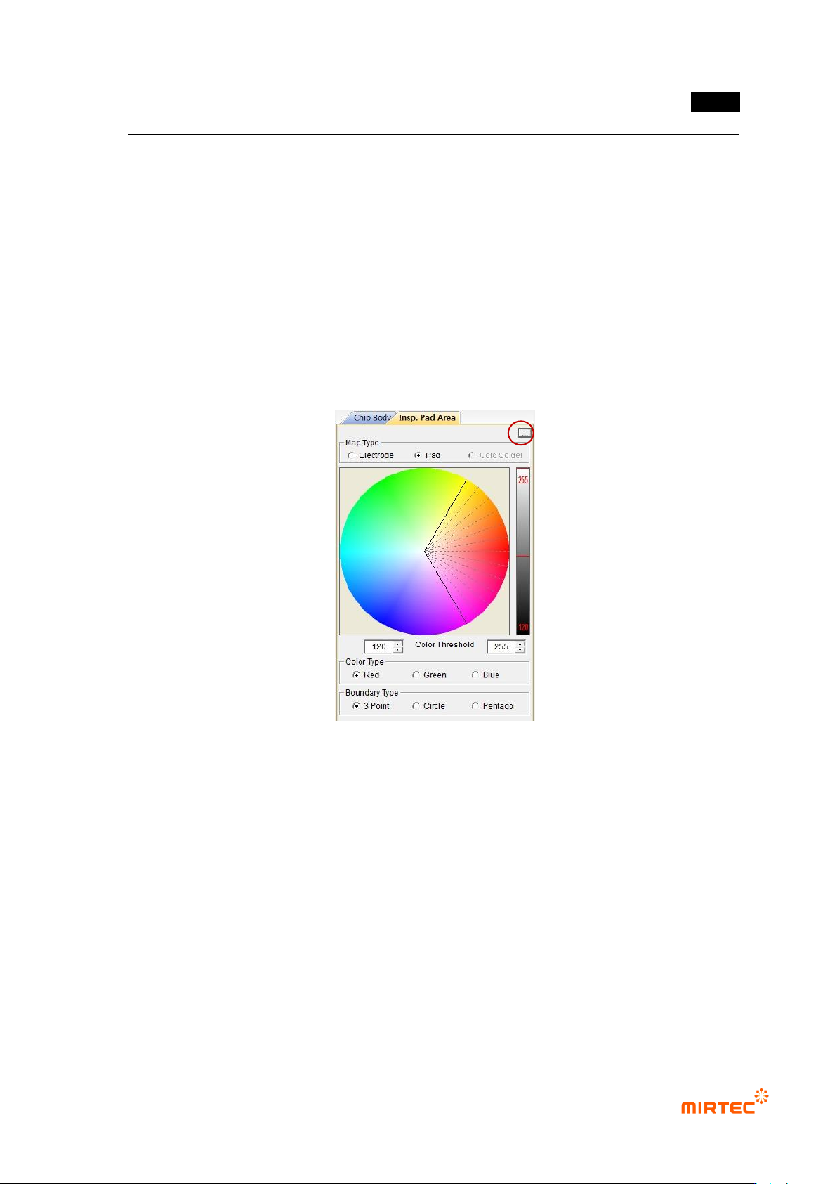
- Color type consists of red, green, and blue. Select color to adjust area desired to be
binarized for each color.
- In other words, select color type to red, and set desired red area in color map. Set
luminance range of color extracted by using right bar to extract only red of desired
luminance. Even though it has same luminance, it can be divided into other color. Even
though it has same color, it can be divided into other luminance. This is used to distinguish
substrate from component, and used for division according to side angle of fillet slope in
solder total area.
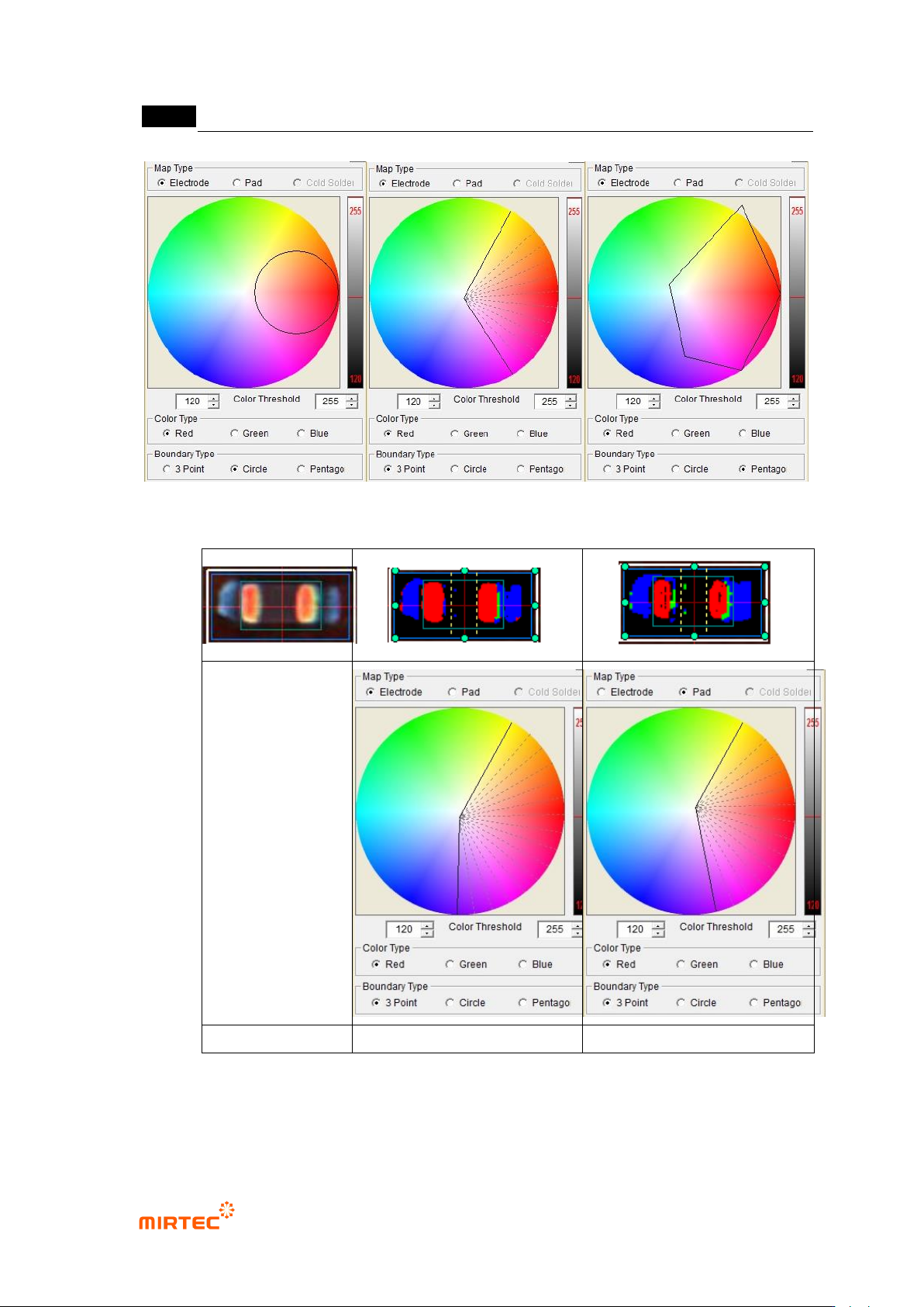
③ Normal boundary region: As shown in [Figure 5-169], type when binarization area is set. 3
points, circle or pentagon can be selected.
[Figure 5-225 color map setting parameter]
MV-9 User Manual
5-184
[Figure 5-226 Example of normal boundary region selection]
chip image
electrode binarization setting
pad binarization setting
[Figure 5-227 Adjustment example of chip electrode and pad color map]
Electrode color ratio

错误!使用“开始”选项卡将 제목 2 应用于要在此处显示的文字。错误!使用“开始”选项卡将 제목 2 应用
于要在此处显示的文字。 .
5-185
- In case there are defects like non-mounting, Manhattan, excessive solder, electrode
damage, foreign material that can occur in electrode area, electrode color ratio is to set
color ratio of electrode and normal range size of electrode to detect defect.
① Red Ratio (%): Set min ratio of Red in extracted electrode area.
② Blue Ratio (%): Set max ratio of Blue in extracted electrode area.
③ Long size (%) -: Set min ratio of normal range of electrode major axis. For example, if
electrode size is 100 and setting value is 30%, normal range of major axis of electrode will
be 70.
④ Long size (%) +: Set max ratio of normal range of electrode major axis. For example, if
electrode size is 100 and setting value is 30%, normal range of major axis of electrode will
be 130.
⑤ Short size (%): Set normal range ratio of electrode minor axis. For example, if electrode size
is 100 and setting value is 60%, normal range of minor axis of electrode will be 40 ~ 160.
⑥ Tilt Angle: set Tilt Angle in normal chip range.
- Electrode defect is for good/defect judgment by comparing area ratio of electrode area
(preview) expressed by red that is extracted in pad inspection → color map → Electrode
with reference value based on area of electrode area extracted from chip body.
- Short size and long size is to detect electrode size defect (electrode damage, non-
mounting, etc).
Short size and long size of electrode is defined by [(real value-reference value)
ⅹ100/reference value]. ratio of minor axis/major axis length of electrode extracted
during real inspection to minor axis/major axis length of electrode of calculated
normal chip during optimization process.
Real value is the size of electrode extracted from body tap for chip that is currently
being inspected, and reference value is saved in optimization and setting stage
during teaching or minor axis length of electrode and electrode major axis length on
the bottom of chip body tap.
(-) display in inspection result means that the size of electrode that is actually
extracted is below reference value.
Non-mounting criteria
- This parameter is to detect non-mounting. If blue area is smaller than setting ratio of
electrode area in area between pad offset and electrode, judge as good.