MV-9_Chapter 5. Teaching.pdf - 第201页
错误 ! 使用“开始” 选项卡将 제목 2 应用于要在此处显示的文字。 错误 ! 使用“开始”选项卡将 제목 2 应用 于要在此处显示的 文字。 . 5- 201 [Figure 5- 250 Center of binary inspection-componen t sear ch inspection setting and preview image] [Figure 5- 251 center of binary inspec…
MV-9 User Manual
5-200
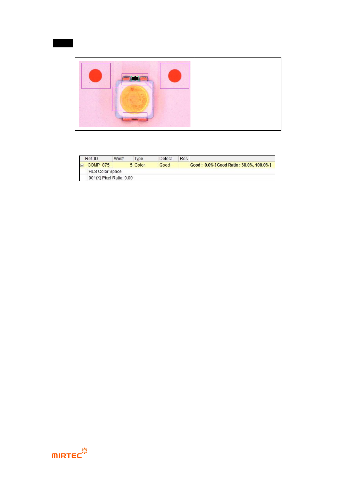
[Figure 5-248 Polarity inspection setting and preview image]
[Figure 5-249 Polarity inspection result]
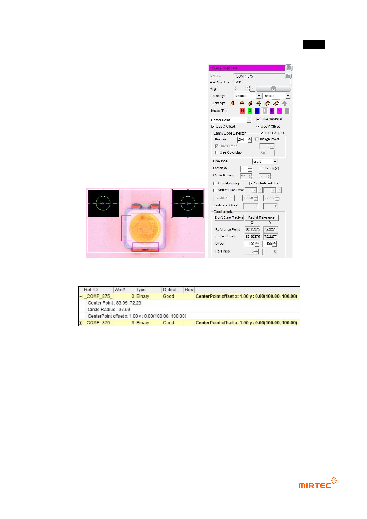
④ Reference point (mark) teaching and setting
- Use center position of circle reference point to inspect X/Y-shift of LED package.
- Create binary inspection window to detect center position of reference point, and select
component center search. select circle or center of gravity (center of gravity) for figure type.
- Check at „Use Subpixel‟. If Cognex license key is installed, check at „use Cognex‟.
- Select „preview‟, and adjust binarization for proper separation of edge of reference point
through color map-setting.
- Conduct trial inspection to display center position of reference point at the current central
point in inspection window. After normally calculating center, click „Register reference
central point‟.
- Set tolerance range as big as possible. reference point is used as criteria to inspect X/Y-
shift of LED package for BLU inspection. Hence, tolerance range is meaningless.
错误!使用“开始”选项卡将 제목 2 应用于要在此处显示的文字。错误!使用“开始”选项卡将 제목 2 应用
于要在此处显示的文字。 .
5-201
[Figure 5-250 Center of binary inspection-component search inspection setting and preview image]
[Figure 5-251 center of binary inspection-component search result]
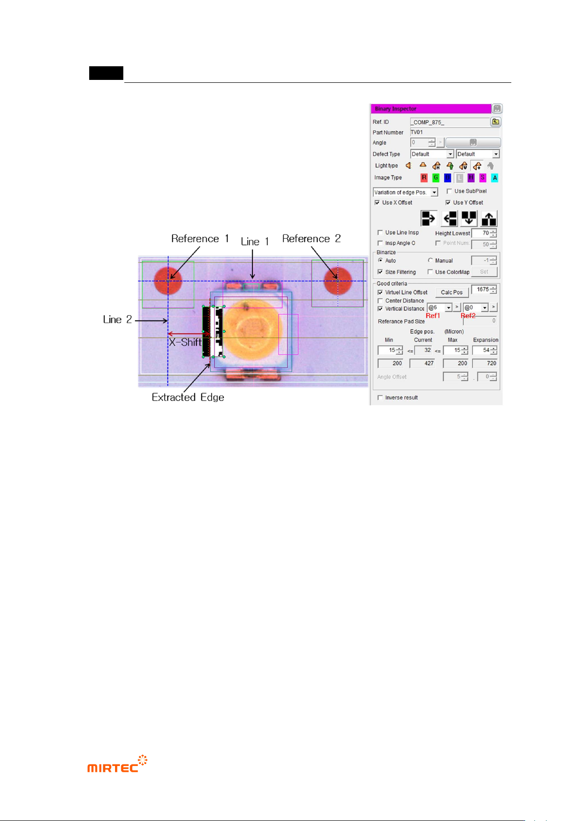
⑤ Teaching and setting for X-shift inspection
- Measurement principle
Straight line 1 that links center of reference point 1 and reference point 2.
Create normal (straight line 2) of straight line 1 based on central point of reference
point 1.
Calculate vertical distance from straight line 2 using x coordinates of extracted
edge, and this calculated value is x-shift measurement value.
MV-9 User Manual
5-202
[Figure 5-252 X-shift definition and inspection setting]
- Setting for X-shift inspection
To inspect X-shift, create binary inspection window on exterior of LED package to
detect edge of vertical direction, and select position move inspection. Draw binary
inspection window to match window center with package edge. Draw window larger
than tolerance*2 to detect edge.
Adjust color map to properly create edge through preview.
Enter „0‟ for min value and window size for max value (If 100 is entered,
automatically changed to max size.) to check if LED edge is properly detected
through trial inspection.
Select „virtual line offset‟ and select „vertical direction distance‟. (Reference: To
select virtual line offset is to create virtual straight line 1 using reference point 1 and
reference point 2, and to select vertical direction distance is to create virtual straight
line 2 and calculate x-shift value.)
Firstly, register window close to package edge to be inspected as reference point 1,
and register reference point 2. (Reference: register reference point close to edge as