MV-9_Chapter 5. Teaching.pdf - 第210页
MV -9 Use r Manual 5- 210 ④ X-shift inspection teaching and setting - Since this m odel has no re ference point for shift in spection, v i rtua l line offs et is n ot use d for binary inspection-p os i tion m ove i nspec…
错误!使用“开始”选项卡将 제목 2 应用于要在此处显示的文字。错误!使用“开始”选项卡将 제목 2 应用
于要在此处显示的文字。 .
5-209
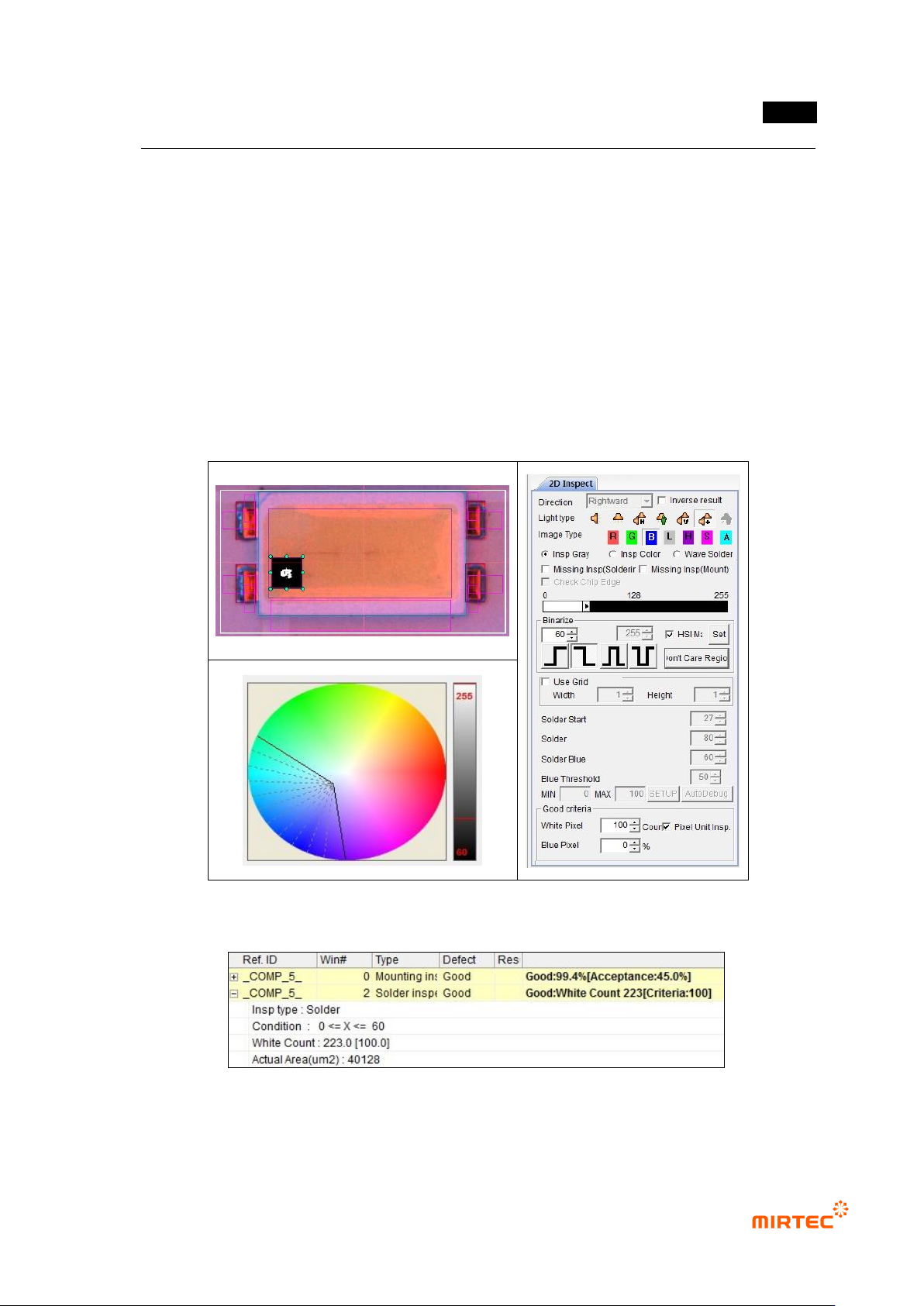
③ Polarity inspection (solder inspection) teaching and setting
- For Polarity inspection, detect polarity of mounted LED package and judge Polarity. In
general, TV has a polarity mark (so called chamfering) on one corner of package. However,
detection status differs from package. Hence, detect electrode inside LED using solder
inspection algorithm.
- Select general inspection, and select light type and image type in which electrode clearly
appears.
- Set color map and binarization value for good electrode separation through preview.
- Select pixel unit inspection, and enter min value for good/defect judgment by pixel unit.
[Figure 5-263 Polarity inspection setting and preview image]
[Figure 5-264 Polarity inspection result]
MV-9 User Manual
5-210
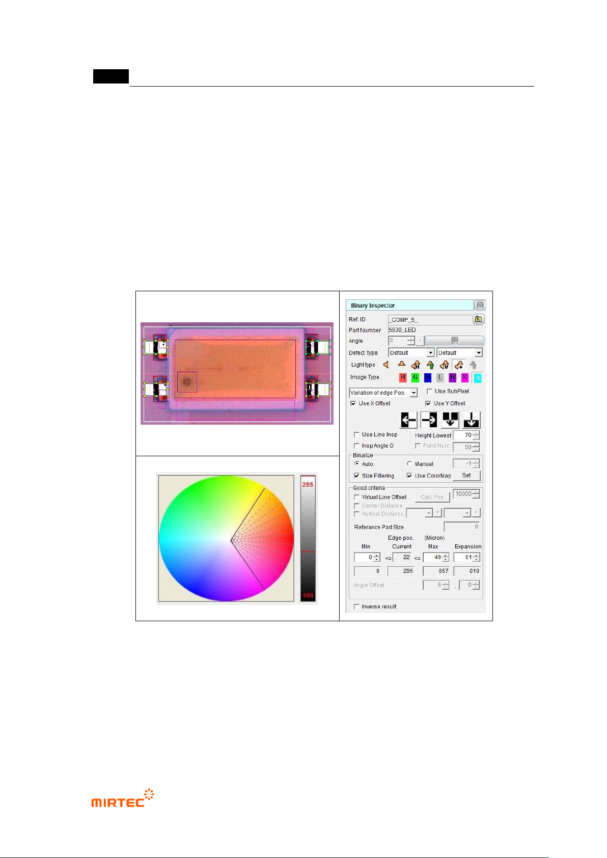
④ X-shift inspection teaching and setting
- Since this model has no reference point for shift inspection, virtual line offset is not used
for binary inspection-position move inspection.
- Create binary inspection window to detect edge of vertical direction at exterior of LED
package for X-shift inspection, and select position move inspection.
- Draw binary inspection window to match window center with package edge. Draw window
larger than tolerance*2 to detect edge.
- Adjust color map and binarization to properly create edge through preview.
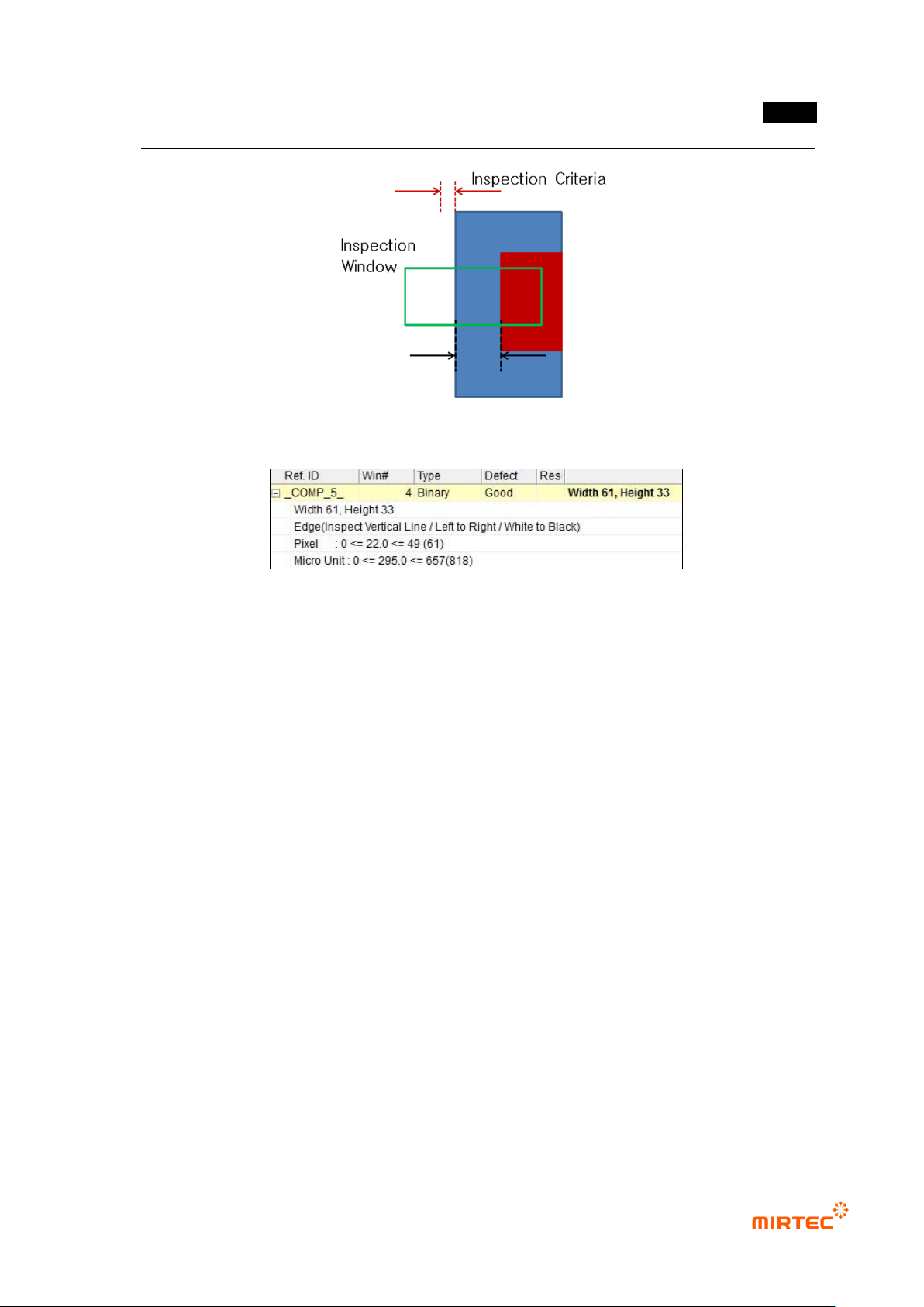
- Enter „0‟ for min in normal criteria, and enter max by adding real distance from lead end to
pad end (unit pixel) to inspection reference value. (Refer to figure 5-282.)
[Figure 5-265 X-shift inspection setting and preview image]
错误!使用“开始”选项卡将 제목 2 应用于要在此处显示的文字。错误!使用“开始”选项卡将 제목 2 应用
于要在此处显示的文字。 .
5-211
[Figure 5-266 Setting max inspection criteria]
[Figure 5-267 X-shift inspection result]
⑤ Teaching and setting for Y-shift inspection
- Teaching for Y-shift inspection use same method for teaching for X-shift inspection.
- Enter „0‟ for min in normal criteria, and enter max by adding inspection reference value
(unit pixel) to real distance from lead end to pad end. (Refer to figure 5-285.)